LEARNING OBJECTIVES
Upon completing this lesson, you should be able to:
- Recognize the marking system.
- Recognize the marking system for a wire to include aircraft and shipboard electronic equipment systems.
- Recall the seven types of electrical diagrams & the functional design of each.
SCHEMATIC READING
This lesson is divided into two subtopics
- Cable and wire-marking systems,
- Electrical and electronic diagrams.
First, we will discuss the systems used for marking cables and wires.
We will explain each type of diagram you will encounter when troubleshooting, testing, repairing, or learning about circuit or system operation.
Cable and Wire-marking Systems
Why Use Cable Labels
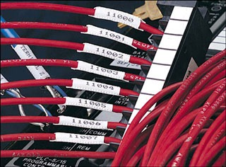 Cable labels are a way to provide a quick, easy method to identify cables clearly.
It’s an affordable method for labeling cables for future cable identification.
A label makes wire easy to read and can be situated so that the label can be easily read in hard-to-reach areas.
With some systems, the marking surface can be rotated 360 degrees for easy viewing.
Why Wire Markers Are Important
Wire markers and cable markers attach to wires and cables.
Wire marking and cable identification have become vital components in most electrical system installations.
This is because of the ever-increasing demands for:
- security
- maintenance upgrade
- trace-ability
Wire markers and cable markers differ widely in terms of product specifications. For example:
• Heat-shrinkable sleeves are often made of polytetrafluoroethylene (PTFE), polyvinylidene fluoride (PVDF), or fluorinated ethylene-propylene (FEP).
- PTFE or FEP sleeves are well-suited for applications that require high resistance to chemicals, solvents, or ultraviolet (UV) light.
• Flex-tag wire markers are designed for bendable wires and cables.
• Rip tags are installed with cable ties instead of with adhesives.
These are a good choice for wire marking or cable marking applications in areas subject to spills of fuels, lubricants, or solvents.
• A hot stamp wire marker allows operators to use one wire guide for a range of harness wires.
• A benchtop laser wire marker is designed to process both single-core wires and multi-core cables.
What Wire and Cable Markers Do
Wire and cable markers attach to wires and cables and help identify them. Many different types of wire markers and cable markers are available.
Basic wire marker and cable marker categories include:
• labels
• sleeves
• tags
Specialized products include:
• laser wire markers
• insert markers
• tie-on cable markers
• hot stamp markers
• number kits
• heat shrinkable sleeves
• shrink-tag markers
• cable identification marker plates
• flex-tag wire markers
• rip tags
Wire and cable markers are used in various applications and industries.
Some products are designed for use with valves, laboratory instruments, motors, and industrial components.
Other wire markers and cable markers are designed for computer cables or electrical wires.
Wire marking and cable marking products for specialized applications are also available.
Cable Tie Labels
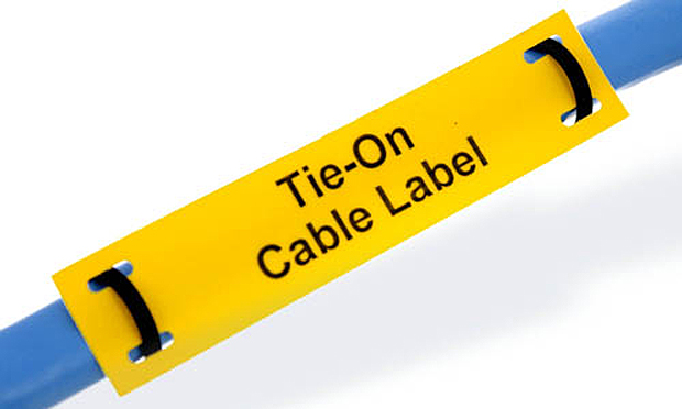 Cable tie labels are labels designed primarily for use on Twinax, coax, or any other cables where labels are seldom moved.
The cable-tie attachment enables the tag to be affixed securely to any size cable and be held in a relatively rigid position for ease of viewing, depending on the tightness of the cable tie attachment.
Cable Installation Don’ts: Before you slap a cable label or wire marker on those cables, you must install them.
When installing cable in a residential or an industrial setting, a few rules should always be followed.
- Do not cut the unlabeled cable. Label the cable before routing it, or you’ll lose track of which cables go to which rooms.
- Do not allow the cable to be stretched, pinched, or kinked, or data will travel over it more slowly.
Also, do not tie tie-wraps too tight – they should ideally be able to slide around a little.
Benefits of a Wrap Labeler 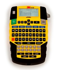
Labelers can put clear, crisp scannable bar codes, graphics, and human-readable text on boxes or other items.
There are industrial wrap labelers that will label both the corner and the side of the product.
The benefits of this are two-fold:
- It reduces label and machinery cost
- It allows for product identification on two sides
Types of Wire Markers
The type of wire marker you use should depend on where you use them and what printing technology you use. For example, for bench/desktop wire and cable markers, it’s best to use blank labels, sleeves, and tags that can be printed using a higher-volume printer.
For pre-printed wire and cable markers, it’s best to use blank or pre-printed labels you can write or print on. Label marker sleeves are an economical and durable solution when you only need two or three digits for identification. For portable printer wire and cable markers, use blank labels, sleeves, and tags that can be printed using lower-volume printers.
Dispensers Keep Labeled Wires in Order
Labels on cables and wires should be legible, durable, reliable, and easy to use. When using labeled wire or cable, you do not want labels to unwind and fall off or become tangled or mixed up. Label dispensers can help to achieve this.
Here’s how two dispensers work:
 Wire Marker Dispenser: among the most user-friendly portable wire marker systems available on the market today.
Each dispenser contains ten rolls of marker tape labeled zero through nine.
Each roll contains 76 individual markers with a pre-determined length to accommodate the most common wire sizes.
Each individual marker is mounted on a silicone release liner and has an acrylic adhesive.
This item is small enough to be hooked on a tool pouch or carried in a shirt pocket.

Rite & Wrap Dispenser: this pocket-sized disposable dispenser contains a roll of pre-cut self-laminating wire markers.
Each marker has a white area for legend inscription using a pen or pencil.
After marking, pull back on the marker liner, and the marker is dispensed.
On application, the transparent portion of the clear vinyl marker wraps around itself to protect the white write-on area.
Do you know the color codes?
To enable wires to be easily and safely identified, all standard wiring safety codes mandate a color scheme for the insulation on power conductors. Some color coding is mandatory, while some may be optional.
Many local rules and exceptions exist.
Older installations vary in color codes, and colors may shift with insulation exposure to heat, light, and aging.
Many electrical codes now recognize (or even require) the use of wire covered with green insulation, additionally marked with a prominent yellow stripe, for safety grounding (earthing) connections.
Color coding makes testing different components within an electrical system far easier.
There should be a key or legend on the wiring diagram to tell you what each color means.
The specific colors for a home electrical system are generally the same across all electrical items.
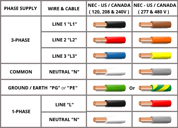
What is the NEC wiring color code?
The most widely adopted code in the world, the NEC was written with safety in mind. It’s the most complete set of electrical code requirements that govern electrical installations. All houses built since the 1940s (and older homes that have been rewired) all subscribe to this cable color coding. If you open an electrical outlet or light switch box, you’ll see multiple wires of different colors that may be grouped together. Each of them serves a different purpose, and it’s critical to know the household wire code to keep yourself safe and your house wiring in optimum working order.
What is the color code for electrical wiring?
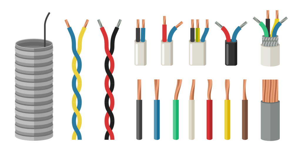
There are two parts to non-metallic electrical cables: the outer sheathing, or jacket, and the inner wires. The colored sheathing covers the inner wires (copper wires). The markings on the outside sheathing indicate the number and gauge of wires inside; the color of the sheathing indicates the purpose.
- Black wires carry power from the electrical service panel to an outlet, light, or other destination. A black wire is considered a hot wire because it carries a live electrical load.
- Red wires are also hot wires and, in a 240-volt installation, are sometimes used as secondary hot wires. These are used to interconnect smoke detectors so that if one alarm goes off, all the others do as well.
- White and gray wires are neutral wires that connect to the neutral bus bar (a conductive piece of metal in an electrical panel that attracts current and carries it throughout the house). Even though they’re neutral, white and gray wires still can carry a current—especially if the current load is unbalanced.
- White wires wrapped in black or red electrical tape are hot wires. The tape just serves as an alert that the normally neutral wire is being used as a hot wire rather than a neutral one. As a precaution, loop the tape around it several times to make sure you know it’s not neutral.
- Green wires ground an electrical circuit. A ground wire connects the grounding terminal in an outlet box and runs it to a ground bus bar in the electrical panel. As a failsafe, the green ground wire gives electric current a place to escape to the ground in the event of a live wire touching metal or something else that is conductive. Green wires can only connect to other green wires and may still be live if there’s a problem or fault in the electrical system.
- Bare copper wires are the most common type of grounding wires.
- Blue and yellow wires, although not usually found in non-metallic (NM) cables, are sometimes used as hot wires in an electrical conduit. Blue wires are travelers commonly used in three- and four-way switch operations, which might be the switches at the top or bottom of a staircase that control the same light.
Know the rules that are used for wiring components together.
 More in-depth information can be found in introductory physics and electronics texts.
Information may also be found on the back of the component packages and some datasheets.
For example, the rules for connecting resistors are different from those of capacitors or inductors.
An extremely important rule for components is that they may be wired in series or parallel.
Points connected by the same wire are at the same potential and are electrically equivalent.
Check your voltage (V).
Main lines are represented by L1, L2, and N.
Look to see which main lines appear on your wiring diagram.
- If your diagram has L1 and N, it is a 110V circuit.
- If your diagram has both L1 and L2, it is a 240V circuit.
- If your diagram has L1, L2, and N, it is a 110-240V circuit.
Recognize the difference between polarized and non-polarized components.
Like voltage sources, some components are also polarized. The way they are placed into the circuit with respect to the voltage source is important, while others are independent of their circuit direction. Some capacitors are polarized, while resistors are not.
Learn the most common fundamental circuit combinations. There are certain electrical components that are always wired the same way using the same parts. Their role is to form mini-circuits that are used to perform certain tasks for a larger circuit. They may be viewed as building blocks. Examples of such are voltage dividers, diode clamping circuits, and filters.
Once you have mastered the basic analog circuits, you may proceed to logic circuits.
POWER TOOL AND APPLIANCE MARKING SYSTEMS 
As with the wire- and cable-numbering systems discussed so far, there are many color-coding systems used in electrical and electronic applications.
The color-coding system discussed here is to code conductors for power tools and appliances.
An electrical power tool or appliance is required to have a three-wire cable.
The conductors in the cable are color-coded black, white, and green.

One side of the electrical input is grounded.
The grounded side is called the “common” and is color-coded white.
The other side of the input is called the “line,” or hot side, and is color-coded “black.”
The green conductor is connected to the ground and to the frame of the appliance or tool.
The black or the white conductor may be connected to either line since there is no difference.
The green conductor is connected to the ground.
The purpose of the ground wire (green) is to prevent an electrical shock to the operator if there is an electrical short to the frame of the appliance or tool.
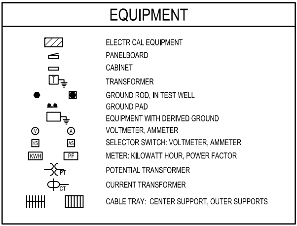
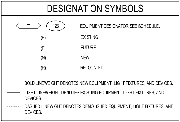
Electrical Symbols
An electrical symbol is a pictogram that represents various electrical and electronic devices (such as wires, batteries, resistors, and transistors) in a schematic diagram of an electrical or electronic circuit.

These symbols can (because of remaining traditions) vary from country to country but are today, to a large extent, internationally standardized.
Some symbols represent components that ceased to be used routinely as newer technologies were introduced (such as vacuum tubes).
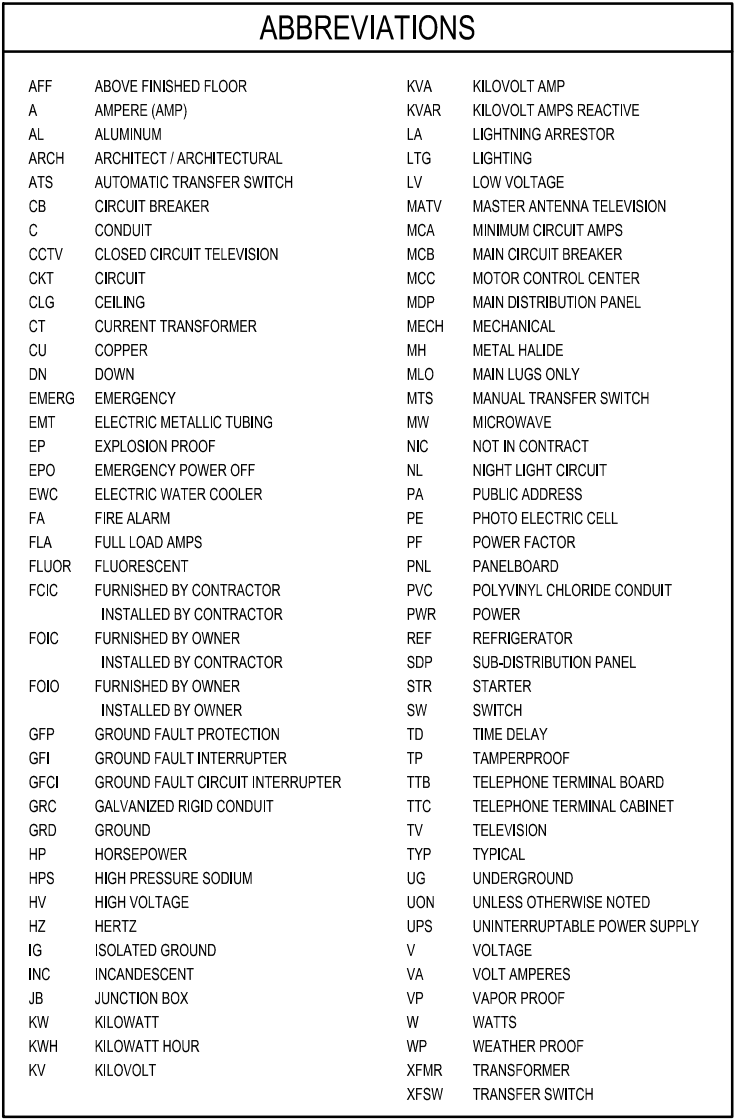
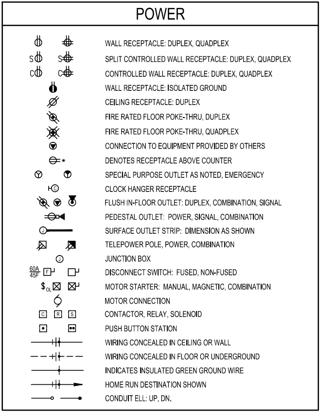
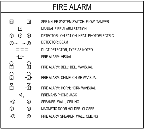
HERE ARE SOME COMMON ABBREVIATIONS AND SYMBOLS

ELECTRICAL DIAGRAMS
In Electrical and Electronics Engineering, we use different drawings or diagrams to represent a particular electrical system or circuit. These electrical circuits are represented by lines to represent wires and symbols or icons to represent electrical and electronic components. It helps in better understanding the connection between different components. Electricians rely on electrical floor plans (which is also an electrical diagram) for doing any building wiring.
Personnel in the electrical or electronic fields must be able to “read” (Interpret) various types of electrical drawings and diagrams.
Personnel working in these fields commonly refer to all electrical diagrams as “schematics.”
This term is not correct, however. A schematic is a specific type of diagram with its own characteristics and a specific purpose.
Each of the various diagrams discussed in this lesson has a specific purpose and distinguishing features that set it apart from the others.
The diagrams discussed may be used for the following purposes:
• To learn a specific system operation
• To locate the components of a system
• To identify the components of a system
• To trace a circuit
• To troubleshoot equipment
• To repair equipment.
When you have completed this review, you should be able to recognize the relationship between the various diagrams, their distinguishing features, and the purpose of each type of diagram.
PICTORIAL DIAGRAM
The simplest of all diagrams is the pictorial diagram. It shows a picture or sketch of the various components of a specific system and the wiring between these components.
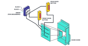
This simplified diagram provides the means to readily identify the components of a system, even if you are not familiar with its physical appearance.
This type of diagram shows the various components without regard to their physical location, how the wiring is marked, or how the wiring is routed.
It does, however, show you the sequence in which the components are connected.
If you are not already familiar with the components of this system, study the diagram.
You should then be able to recognize the physical appearance of each component and its interconnections with the other components of the system.
ISOMETRIC DIAGRAM
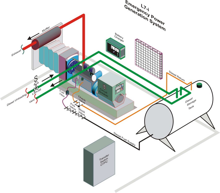
The purpose of an isometric diagram is to assist you in locating a component within a system.
If you do not know where to look for a component, the isometric diagram is of considerable value to you.
Within the outline are drawn the various components of a system in their respective locations.
The isometric diagram also shows the interconnections between these components.
Isometric diagram of an emergency power generation system.
The isometric wiring diagram is not used very often in electrical work. When used, it shows the electrical relationship in multilevel buildings, between floors, or the total electrical system. In the isometric diagram, the cable and fixtures are shown only in their general location. Their exact locations are given in the electrical prints.
BLOCK DIAGRAM
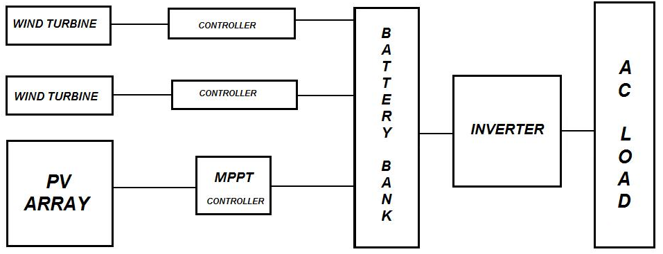
A block diagram is a type of electrical drawing that represents the principal components of a complex system in the form of blocks interconnected by lines that represent their relation. It is the simplest form of electrical drawing as it only highlights the function of each component and provides the flow of process in the system.
A block diagram is a diagram of a system, in which the principal parts or functions are represented by blocks connected by lines that show the relationships of the blocks.
They are heavily used in the engineering world in hardware design, electronic design, software design, and process flow diagrams. They are used to present a general description of a system and its functions.
The block diagram is typically used for a higher level, less detailed description aimed more at understanding the overall concepts and less at understanding the details of implementation.
Block diagrams are easier to design and are the first stage in designing a complex circuit for any project. Why do electricians not rely on block diagrams? It lacks information about the wiring and placement of individual components. It only represents the main components of the system and ignores any small components.
SINGLE-LINE DIAGRAM
The single-line diagram is used basically for the same purpose as the block diagram.
When used with text material, it gives you a basic understanding of the functions of the components of a system.
There are two major differences between the single-line diagram and the block diagram.
The first difference is that the single-line diagram uses symbols, rather than labeled blocks, to represent components.
Second, the single-line diagram shows all components in a single line.
There are no interconnections shown for selected components as shown on the block diagram.
The single-line diagram is very simplified and should be used primarily to learn (in very broad terms) the function of each of the various components as a part of the total system.
A single-line diagram also referred to as a one-line diagram, is usually a single-page document that represents a facility’s electrical distribution infrastructure. It will have one single line shown for the bus (or cable) to represent all three-phase.
Schematic Diagram
A schematic diagram is a circuit that shows the connections in a clear and standardized way. A schematic diagram shows the components and their values and connections in an understandable manner. It is usually used to communicate or intended to convey the connections and workings of the circuit to other engineers.
A schematic diagram is a circuit diagram of a given electronic assembly, describing its circuit flow with all the components used in it. it’s used by qualified technicians to fix it.
The schematic diagram is used to trace the circuit and its functions without regard to the actual physical size, shape, or location of the component devices or parts.
The schematic diagram is the most useful of all the diagrams in learning overall system operation.
In an electronic circuit diagram, the layout of the symbols may not resemble the layout in the physical circuit.
In the schematic diagram, the symbolic elements are arranged to be more easily interpreted by the viewer.
The circuit diagram is the one neatly presented in the books systematically. Pretty useful for understanding the theory and workings of the circuit. But this is not useful for a wireman/electrician. He wants to see the actual switch contact, their numbering, etc, in an implementable way. He is more implementation-oriented. He needs a wiring diagram.
WIRING DIAGRAM
The wiring diagram is used for the representation of electrical components in their approximate physical location using their specific symbols and their interconnections using lines. Vertical and horizontal lines are used to represent wires, and each line represents a single wire that connects between electrical components.
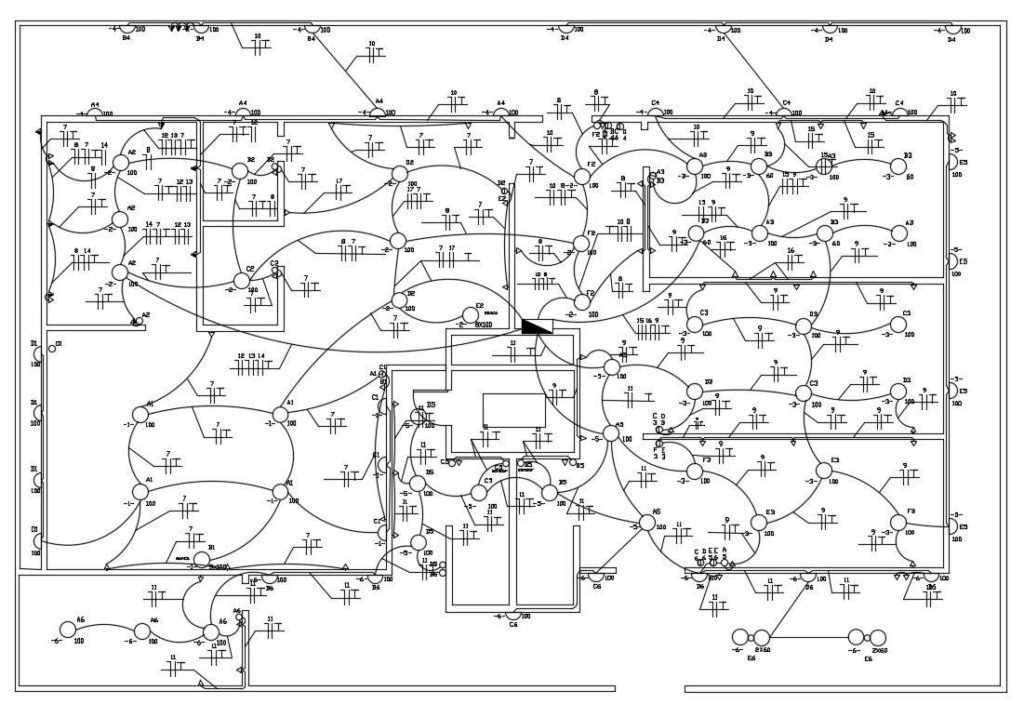
The wiring diagram shows a pictorial view of the components such that it resembles their electrical connection, arrangement, and position in a real circuit. It really helps in showing the interconnections in different equipment such as the electrical panel and distribution boxes etc. they are mostly used for wiring installation in homes and industries.
The wiring diagram is the best method for system designers to feed information to the installers. Whether it is a building, electronic circuitry, or cross-country transmission, everyone involved in a project can look at the wiring diagram and know how it is supposed to be done.
It also identifies the wires by wire numbers or color-coding.
Wiring diagrams are necessary to troubleshoot and repair electrical or electronic circuits.
RISER DIAGRAM
The riser diagram is the illustration of the physical layout of electrical distribution in a multilevel building using a single line. It shows the size of conduits, wire size, circuit breaker rating, and other electrical devices (rating of switches, plugs, outlets, etc) from the point of entry up to the small circuit branches on each level. It shares the layout with an alarm system as well as telecom and internet cables.

The riser diagram got its name because it illustrates the power flow from one level to another. It does not specify the physical location of the equipment and does not contain unnecessary information.
Continue to the next lesson where we discuss construction drawings.