CONSTRUCTION DRAWING TUTORIAL
OBJECTIVES
Reading construction blueprints consists essentially of finding information on prints. The information may be displayed on a drawing in the form of lines, notes, symbols, and schedules. The items are typically located either in the title block or in the field of the drawing (i.e., anywhere within the borderlines outside the title block).
You should also keep in mind that blueprints typically come in sets. A set of prints for a single-family residence may contain no more than a few sheets, whereas on a large project a complete drawing set may contain scores of sheets for different disciplines (e.g., architectural, structural, electrical, mechanical, plumbing, etc.).
The general process and sequence for reading blueprints:
- Verify that the set of drawings and specifications is complete. Likewise, verify that the documents in hand are the most current.
- Start by reviewing the site or plot plan to better comprehend the setting of the building and the general topography.
- Visually scan the architectural drawings to get a better overall understanding of the project. Look at the title block to extract any general information pertaining to the project that may be needed (consultant’s name, client’s name, project title, drawing number, etc.).
- Check for unusual or complicated features that may impact how the building is constructed. Review the elevations and sections and the materials used.
- Review the foundation plan and read the general notes to better understand the construction specifications and other information relevant to the drawing. Also, look at the relevant building details.
- Review the structure’s wall construction and the material and methods used. Also, study the details showing how the wall is to sit on the designed foundations and which walls if any are load-bearing and which are not.
- Review the plumbing, mechanical, and electrical drawings.
- Check all notes on these plans to see if there have been any revisions. Check to see if the building codes have been taken into account. Ensure that the notes on the drawings are clear and that there is no ambiguity.
- Review the specifications and compare them to the drawings. (Specifications normally have priority over drawings.) If there are discrepancies, the consultant should be notified.
Types of Construction Drawings
Construction drawings are generally categorized according to their intended purpose.
- Types commonly used in construction may be divided into five main categories based on the function they intend to serve:
-
- Preliminary drawings
- Presentation drawings
- Working drawings
- Shop/assembly drawings
- Specialized and miscellaneous drawings
Working Drawings
Also called constructions drawings, working drawings include all the drawings required by the various trades to complete a project. These drawings are technical and are intended to furnish all the necessary information required by a contractor to erect a structure. Working drawings show the size, quantity, location, and relationship of the building components.
Working drawings serve many functions: However, we are going to be concentrating on the purpose of this manual:
- They are the means for receiving a building permit. Before construction begins, the local building authority must review the working drawings to ensure that they meet required building codes and meet public safety requirements in terms of structural soundness, fire, and other hazards. A building permit will be issued after the approval of the drawings.
The pages in a set of blueprints are usually carefully lettered and numbered. The letters shown here are the ones most commonly used in the industry:
- A: Architectural pages
- S: Structural pages
- P: Plumbing pages
- M: Mechanical pages
- E: Electrical pages
If a set of blueprints consist of 25 pages, it may be numbered as follows: A1 through A8 (eight architectural pages); S1 through S10 (five structural pages); P1 through P3 (three plumbing pages); M1 through M4 (four mechanical pages); E1 through E5 (five electrical pages).
Most construction drawings consist of orthographic views which are two-dimensional views of three-dimensional objects.
- General drawings consist of plans and elevations drawn at a relatively small scale.
- Detail drawings consist of sections and details drawn at a relatively large scale.
- A plan view is a view of an object or area as it would appear if projected onto a horizontal plane passed through or held above the object area.
- The most common construction plans are plot plans or site plans, foundation plans, floor plans, and framing plans.
- A plot plan shows the contours, boundaries, roads, utilities, trees, structures, and other significant physical features on their sites. The locations of the proposed structures are indicated by appropriate outlines or floor plans.
Construction drawings are legal documents.
Cover Sheet
The first sheet in a set of working drawings is the cover sheet. Depending on the size of the project the cover sheet can and will have different sections. You read plans much like you would a book, starting in the upper left-hand corner and reading the sections left to right.
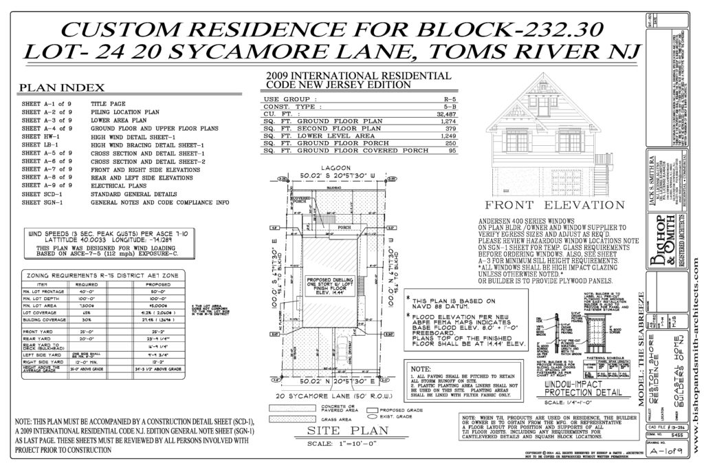
NOTE on the drawing above:
- Plan index lists the drawings that comprise the set in the order that they appear.
- Specific requirements of the building code that has jurisdiction over the design of the project.
- USE group the structure will fall under, and the type of construction. The information required includes the total square footage of the structure. It will give you the square footage of each floor.
- On the far right side, It lists the project name and location, building permit information.
- Zoning requirements.
- List of abbreviations or graphic symbols used in the set. (As you will see later these can be on each page of the drawing. For larger projects, they are on the first page of the industry.
- Sections that contain general notes for the contractor, such as “Do not scale” or “All dimensions to be verified on site.”
Plot Plans/Site Plans
A site or plot plan is a scaled drawing of a property that shows its size and configuration including the size and location of man-made features such as buildings, driveways, and walkways on the property. Plot plans show both what currently exists and what improvements are proposed. You can typically find the site plan on the cover sheet in small projects.
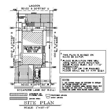
- The main function of a basic site or plot plan is to determine the placement of the structure as it sits in reference to the boundaries of the construction site. Site plans clearly establish the building’s dimensions, usually by the foundation’s size and the distances to the respective property lines.
- Setback dimensions are shown in feet and hundredths of a foot, as opposed to feet and inches on architectural drawings. Thus, an architectural dimension reading 40 feet, 6 inches would be 40.5 feet on a site plan.
- A site plan includes not only the project but also the surrounding area. Site plans should outline the location of utility services, setback requirements, and easements. Topographical data is also sometimes indicated, specifying the slope of the terrain. The grades at fixed points are shown throughout the area to show the land slope before construction is started and the finished grade after construction is completed.
Floor Plans
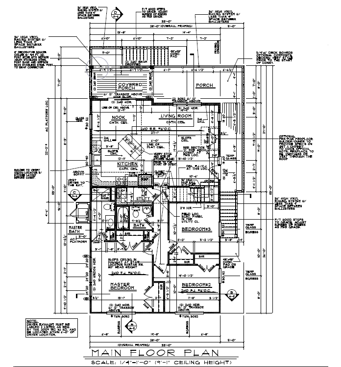
- A floor plan is a part of the architectural drawing that represents a view of the project from above. The floor plan is the most common type of plan view. A floor plan is a two-dimensional view of a space, such as a room or building.
- It is a view of the space from above as if the space were cut through horizontally at the windowsill level with the upper half removed.
- You are looking down at the floor. In general, a floor plan’s main function is to identify and delineate the use of space.
- It identifies the locations and sizes of components such as rooms, bathrooms, doors, windows, stairs, elevators, means of egress, and room access.
- The floor plan will also show the locations of walls, partitions, doors, washrooms, and built-in furniture as well as dimensions and other pertinent information.
- Plans are typically drawn to scale.
- The most common scales for floor plans (depending on size of project) are one-eighth inch = one foot (scale: 1/8 inch = 1 foot, 0 inches) and one-quarter inch = one foot (scale: 1/4 inch = 1 foot, 0 inches). The plan scale should always be noted on the drawing.
Elevations
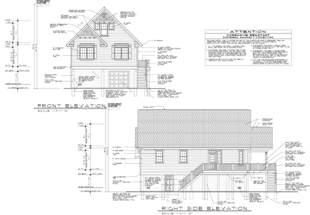
Elevations are an important component of the construction-drawing set and the design and drafting process. Elevations are views that show the exterior (or interior) of a building. They represent orthographic views of an interior or exterior wall. They are flat, two-dimensional views with only the height and width obvious.
Exterior elevations provide a pictorial view of the exterior walls of a structure and indicate the material used (stone, stucco, brick, vinyl, etc.), the location of windows and doors, the roof slopes, and other elements visible from the exterior.
Elevations are usually identified based on their location with respect to the headings of a compass (north, south, east, and west elevations). Or they may be labeled front, rear, right, and left elevations.
Four elevations are normally required to show the features of a building unless the building is of irregular shape, in which case additional elevations may be required.
The main function of exterior elevations is to provide a clear depiction of the façade treatment of the building and any changes in the surface materials within the plane of the elevation. They also show the location of exterior doors and windows (often using numbers or letters in circles to show types that correspond to the information provided in the door and window schedule).
Elevations are typically drawn to the same scale as the floor plan. The scale of the elevation is noted either under or to the side of the title of the elevation or in the title block.
A common scale is one-quarter inch = one foot (scale: 1/4 inch = 1 foot, 0 inch), although a scale of one-eighth inch = one foot (scale: 1/8 inch = 1 foot, 0 inches) is used for larger buildings.
While floor plans show horizontal measurements of elements, elevations mainly provide vertical measurements with respect to a horizontal plane.
These dimensions provide a vertical location of floor-to-floor heights, windowsill or head heights, floor-to-plate heights, roof heights, or a variety of dimensions from a fixed horizontal surface. These measurements can be used to calculate quantities of materials.
Structural Drawings
The structural drawings provide the reader with a view of the structural members of the building and how they will support and transmit its loads to the ground and are usually numbered S-1, S-2, S-3. In a set of working drawings, they are usually located after the architectural drawings.
For new construction: structural-engineering drawings will be needed for foundation and footing details, the structural frame design, beam sizes, and connections.
For concrete structures: the structural drawings will indicate concrete forming details, dimensions of members, and reinforcing-steel requirements. If the structure is steel-framed, the size and type of steel framing will be indicated.
Benefits of structural drawings: they provide information that is useful and can stand alone for sub-trades such as framers and erectors. The structural drawings clearly indicate main building members and how they relate to the interior and exterior finishes without providing information that is not necessary for this stage of construction.
Structural drawings start with the foundation plans, ground or first-floor plans, upper-floor plans, and roof plans.
Only information pertinent to the structural systems is shown. For example, a second-floor structural plan would show the wood or steel framing and the configuration and spacing of load-bearing members but not doors or non-load-bearing partitions.
Following the plan views are the sections and details in the same basic format as in the architectural drawings. Schedules are used to record such information as footings, columns, and trusses.
Foundation Plan
A foundation plan is a plan view of a structure projected onto an imaginary horizontal plane passing through at the level of the top of the foundation.
A foundation sheet:
- Will indicate the size, thickness, and elevation of footings (footers), with notes regarding the placement of reinforcing bars (rebars).
- It will typically note locations for anchor bolts or weld plate embeds for structural steel and other elements.
- The footing schedule is normally found on the first sheet of the structural notes, which also includes notes regarding the reinforcing requirements and other written statements for structural strengths and testing requirements.
To be able to properly interpret a foundation plan, you must first view the other plans, such as the sections and roofing plan.
Framing Plan
The framing plan will indicate the material used for framing the building and may include wood or metal studs, concrete-masonry units, or structural steel.
Framing drawings include:
- The basic skeletal structure of the building is drawn to scale.
- Floor-joist locations, walls, and roof trusses are part of the overall detail of these plans.
- Locations of each stud are not included, since the process is standard.
- In some cases, there are instructions for particular wall-construction methods.
- Intermediate structural framing plans are used for multistory construction, where each level may require support columns, beams, joists, decking, and other elements.
- Structural drawings typically incorporate numerous details relating to the structure.
MECHANICAL DRAWINGS
The cover sheet for mechanical drawings should contain appropriate notes, legends (chart or table of symbols and abbreviations), and details. The mechanical plan specifies the design of or the modifications to the mechanical system, ductwork layout and dimensions, mechanical equipment location, damper locations, design air-delivery rates, diffuser locations, thermostat locations, and supplemental cooling systems if required. Mechanical plans are normally identified as M-1, M-2, M-3.
The mechanical drawings provide the client, the builder, and the permit department with the complete HVAC layout for the job.
The following are typically included in a set of mechanical drawings:
- Plans show the size, type, and layout of ducting
- Diffusers, heat registers, return-air grilles, and dampers
- Turning vanes and ductwork insulation
- HVAC unit types, quantities, and location
- Thermostat types, quantities, and location
- Electrical, water, or gas connections
- Ventilation and exhaust fans
- Symbol legend, general notes, and specific keynotes
- Heating and/or cooling load summary
Depending on the complexity of the project, may include:
- Connection to existing systems
- Demolition of part or all of existing systems
- Smoke detector and firestat for ducting
- Thermostat programming
- Heat-loss and heat-gain calculations per area
- Round-duct, turning-vane, and lay-in-diffuser details
- Special conditions, such as seismic restraint codes
PLUMBING DRAWINGS
Plumbing drawings provide all pertinent information on the design of the plumbing system for a project, including line sizes and location, fixture location, isolation valves, storage-tank capacities, hot-water heater capacities, and locations and drain locations and routing.
Plumbing systems involve two major components, water supply, and drainage. Water is supplied under pressure through pipes to plumbing fixtures. Drainage works by gravity: Drain pipes must slope downward. Vent pipes are required.
A plumbing floor plan will typically show the location and type of plumbing fixtures, as well as the route pipes, which will be run (overhead or through walls) for potable water, drainage, waste, and vents. Plumbing drawings are usually numbered P-1, P-2, P-3.
Plumbing drawings are typically part of the construction-drawing set. In most cases, they are submitted with the construction drawings for a building permit application. They are used for construction. All related plumbing lines; drains, connections, and vents must be installed according to the approved drawings.
The following are typically included in a set of plumbing drawings:
- A plan with lines and symbols representing all piping
- Symbol legend, general notes, and specific keynotes
- Fixture schedule, specifying the manufacturer and model for each item
- The sizes for all piping, cold/hot water, sanitary, vent lines, etc.
- Diagrams, such as water riser and sanitary stack
- Information regarding the water heater
Other information may be needed, depending on the complexity of the project:
- Details drawings, such as water heater, water meter connection, or floor drains
- Diagrams or details referencing special equipment requirements
- Fire-protection notes
- Fire-sprinkler notes and symbols
- Special-air lines
- Natural-gas lines
ELECTRICAL DRAWINGS
The electrical drawings show the various electrical and communication systems of the building, and they provide the client, the builder, and the permit department with the complete power layout for the project.
The electrical cover sheet indicates all electrical specs, notes, and panel schedules. This sheet includes the specification of supplemental electrical panels if required. These drawings are typically part of the construction-drawing set.
They typically include electrical power and lighting plans, telecommunications, and any specialized wiring systems such as fire or security alarms.
Electrical drawings show the location of electrical circuits, panel boxes, and fixtures throughout the building, as well as switchgears, subpanels, and transformers when they are incorporated into the building.
The electrical drawings are submitted with the construction drawings for a building permit application. In some cases, they are submitted separately to obtain an electrical permit. Electrical plans are normally numbered E-1, E-2, E-3.
The National Fire Protection Association publishes the National Electrical Code, which specifies the design of safe electrical systems. They should also be familiar with any state or local codes that apply.
The following are typically included in a set of electrical drawings:
- Type and location of the outlet, (duplex, dedicated, isolated ground, GFI, etc.)
- Size and type of conduits (data, communication, phone)
- Volts of switches, wiring, and circuitry
- Lamps and model numbers of light fixtures
Other information may be needed, depending on the complexity of the project:
- Direct connections (junction boxes, etc.)
- Emergency lighting and exit signs
- Alarm and security systems
- Fire-alarm systems
- Sound systems, speakers, monitors, and cameras
- Special equipment (kitchen, entertainment)
- Special technical devices (computers, gauges, medical, etc.)
- Special wiring (signs, heating, saws)
MISCELLANEOUS DRAWINGS
Details
Detail drawings provide information about specific parts of the construction drawings and are on a larger scale than general drawings. They show features that do not appear at all or are on too small a scale in general drawings.
A detail contains both graphic and written information. An area of construction is drawn at a larger scale to clearly show the materials, dimensions, method of building, desired joint or attachment, and so on.
Details are often drawn as sections. It is as if a slice is made through a specific area and the inner components are visible.
Detail drawings are one of the most important sources of information available to the contractor about specific parts of the construction.
Details are always drawn to scale. A typical scale for detail is 3 inches to 1 foot (scale: 3 inches = 1 foot, 0 inches). The scale for each detail will vary depending on how much information is required to make the construction clear to the builder. Each detail will be titled with the scale noted below it.
Please refer to the Electrical plans document on page 10 to view a Details drawing.
Single Line Diagram
The definition of a single-line diagram or SLD is an electrical diagram or drawing that represents the components of an electrical installation system represented by symbols, and describes how the components are related. Sometimes a single line drawing or diagram of an electrical installation is also called a one-line diagram.
Please refer to the Electrical plans document on page 11 to view a Single Line drawing.
Symbols Used in Construction Documents
Are used to show how a building, object, or system is to be constructed, implemented, modified, or repaired. One of the main functions of graphic symbols on construction drawings is to reference other drawings within the set. For example, a circle drawn around an area of a drawing with an extension to a number would indicate that this portion of the drawing has been drawn to a larger scale to provide more information than would be possible at the existing scale.
Visualizing and reading construction drawings, therefore, necessitate knowledge of symbols and abbreviations used in the construction industry and of their proper use in representing materials and other components and their locations. Symbols may vary slightly from one locale to another.
Most drawings have a symbol list or legend drawn and lettered either on each set of working drawings or in the written specifications. They are typically located on the first page of the
For this system of symbols to work, each drawing within the set has its own unique number. This is usually a combination of numbers: the number for the drawing as well as the page or sheet number on which the specific drawing appears. Individual drawings may be referenced many times throughout a set of construction drawings.
The symbols discussed in this manual are not all-inclusive by any means, but they are the ones that the builder or designer is likely to encounter in most general building-construction applications.
Graphic symbols are often used on building plans to show elements such as gas and water service lines and window types as well as to list drawing notes and identify finishes and revisions. The same graphic can be used for more than one purpose. Trade-specific symbols are included for the electrical, HVAC, and plumbing trades. The legend on a drawing should show any nonstandard symbols and their meanings.
Indexing Symbols
To summarize, when reading symbols on a blueprint, the following should be remembered:
- Placement of symbols on floor plans and elevations may be approximate unless they are dimensioned.
- Do not scale a symbol to determine its size. Specific information should be obtained from relevant details, schedules, or specifications.
- A symbol’s size may vary according to the scale of the drawing.
- Symbols drawn to represent surface materials may cover only a representative portion of an area.
- Abbreviations are often used in place of a graphic symbol to reduce drawing time and space.
- Symbols for the same items are usually different in plan, elevation, and section drawings.
- Some symbols may use the same or similar graphic treatments in elevation. Check notations, detailed drawings, and specifications for identification.
Please refer to the Electrical plans document on page 1 notice that there is a section for abbreviations and sections showing the different symbols you will see within that set of drawings.
Understanding Schedules
A schedule as applied to construction working drawings is an organized method of presenting general notes or lists of materials, building components (doors, windows, etc.), equipment, and so forth in a drawing in tabulated form.
The main purpose of incorporating schedules into a set of construction documents is to provide clarity, location, sizing, materials, and information on the designation of doors, windows, roof finishes, equipment, plumbing, and electrical fixtures.
- Schedules and specifications give specific details about actual items, while drawings generally show the size and location of the item.
- Schedules are generally organized in a drawing set such that they are near the discipline to which they are related.
There are several different approaches to setting up a schedule; it may include all or some of the following information about the product:
- Vendor’s name
- Product name
- Model number
- Size
- Quantity
- Rough opening size
- Material
- Color
Many different items or features may be described in schedules: some examples are, doors, windows, lintels, columns, beams, electrical equipment or fixtures, plumbing and mechanical equipment, room finish information, and appliances.
Schedules are tables that list information about specific items and allow you to quickly refer to a specific item.
LIGHTING FIXTURE AND ELECTRICAL SCHEDULES
Lighting-fixture schedules are generally used to list the fixture types and identify each fixture type on the drawing of a given project by number. The manufacturer and identification number of each type are given along with the number, size, and type of the lamps for each. One can include a “mounting” column to indicate whether the fixture is wall-mounted, surfaced-mounted on the ceiling, or recessed.
Please refer to the Electrical plans document on page 2 to view the Luminaire Schedule and Panel Schedules can be found on pages 12-13.
Alternatively, this information can be included in the “remarks” column. Also included in this column is information relating to the mounting height above the finished floor, in the case of a wall-mounted lighting fixture, or any other pertinent data for the proper installation of the fixtures.
Electrical general notes are placed on the first and subsequent sheets of the electrical drawings. Electrical notes are normally contained on each sheet as required and are relevant to that sheet only. They are also used to give specific locations and directions regarding electrical issues.
Panel-board schedules are generally found on electrical drawings and are used mainly to indicate relevant information on the service-panel boards within the building. A panel-board schedule should provide enough data to identify the panel number (as indicated on the drawings) and the type of cabinet (whether surface-mounted or flush). It should also provide relevant data regarding the panel main bus bars and/or circuit breakers as well as the number and type of circuit breakers contained in the panel board and the components fed by each.
Why is a mechanical equipment connection schedule included in the electrical drawings? Because they have electrical characteristics and the electrical needs to be provided for this equipment. Be sure to read the General notes and Notes sections on this page.
Please refer to the Electrical plans document page 3 to view a Mechanical Equipment Connection schedule.
NOTES
Notes are a pivotal aspect of construction drawings, as they often contain critical information regarding the project. They do not typically contain technical information but rather clarify and explain the conditions or requirements of the project.
There are two basic types of notes:
- General notes are usually placed at the beginning of the drawings relating to a specific trade or discipline. They include all notes on the drawing not accompanied by a leader and an arrowhead. They are used essentially to explain and specify certain conditions relative to that discipline or the project as a whole.
- Keynotes are contained on a particular page or sheet as needed and relate only to that sheet.
Please refer to the Electrical plans document paying particular attention to all the notes on the different pages.
SPECIFICATIONS
Specifications are sheets of paper, gathered into a pamphlet (or into several volumes for a large building) covering several subjects in detail. These subjects include information, in paragraph form, that describes the building to be constructed, the materials to be used, and the responsibilities of those involved. The simplest type of construction job should have specifications. They are included with prints and a written contract to become the basis for agreement between the owner and the contractor.
Complete specifications are written to give detailed information about the job. This information cannot conveniently be shown on a set of prints because it is too lengthy. The general purpose of specifications includes the following:
- Provides the general conditions giving the broad provisions of the contract and outlines the responsibilities of the owner, architect, contractor, and subcontractors. Performance guarantees are included.
- Supplement the working drawings with detailed technical information about the work to be done, specifying the material, equipment, and fixtures to be used.
- Provides a written description Working drawings show all walls, partitions, details, electrical devices and equipment, and other features of a building using lines, symbols, and conventional representations. With few exceptions, each part is located by precise dimensions. However, to develop accurate cost estimates and to quickly solve problems that may arise during the construction process, information is shown on the prints in the form of notations. Also, additional information is included in the specifications. Specifications may consist of a few sheets of paper or a book of several hundred pages, depending on the complexity of the project.
- Specifications serve, with the contract agreement and the prints, as the legal basis for the transaction of erecting the building from start to finish. Specifications are intended to supplement the set of prints with data that will spell out the job in a general sense. They also include the details of the job to be done by each individual trade. The set of prints and the specifications are intended to be in agreement. In the event of any discrepancy or conflict between the two, the specifications take precedence. Specifications provide the contractor and subcontractors with detailed information for precise and competitive bidding when estimating the costs of labor and material. Subcontractors bid their work based upon codes referenced in the specifications. For example, electricians comply with the requirements of the NEC then estimate the cost for specific materials.
- The building department of the town or city in which the building is to be constructed uses the specifications and the prints to determine their compliance with all applicable building codes and zoning ordinances to meet structural, fire, and health standards.