Introduction
Introduction to matter, energy, and electricity introduces the course with a short history of electricity and electronics and proceeds into the characteristics of matter, energy, and direct current (DC). It also describes some of the general safety precautions and first-aid procedures that should be common knowledge for a person working in the field of electricity.
Matter, Energy, and Electric Fields
If there are roots to Western science, they undoubtedly lie under the rubble of what was once ancient Greece. Except for the Greeks, ancient people had little interest in the structure of materials. They accepted a solid as being just that, a continuous, uninterrupted substance. One Greek school of thought believed that if a piece of matter, such as copper, were subdivided, it could be done indefinitely, and still, only that material would be found.
Others reasoned that there must be a limit to the number of subdivisions that could be made to material and have the material still retain its original characteristics. They held fast to the idea that there must be a fundamental particle upon which all substances are built.
Recent experiments have revealed that there are, indeed, several basic particles or building blocks within all substances.
The following explains how substances are classified as elements and compounds and made up of molecules and atoms. This lesson then is a tutorial about protons, electrons, valence, energy levels, and the physics of electricity.

Democritus and the atom: c.420 BC In the late 5th century BC, Democritus set out an interesting theory of elemental physics. Other Greek thinkers have hinted at notions of a similar kind but never so fully elaborated.
Democritus’s theory states that “all matter is composed of eternal, indivisible, indestructible, and infinitely small substances which cling together in different combinations to form the objects perceptible to us.”
The Greek word for indivisible is atomos, and this theory gives birth to the atom.
Democritus describes an extraordinary beginning to the universe. He explains that initially, all atoms were whirling about chaotically until collisions brought them together to form ever-larger units – including eventually the world and all that is in it.
His theory found few followers over the centuries. But his imagination provides an astonishing first glimpse of the Big Bang Theory.
Matter
The definition of matter is anything that occupies space and has weight; i.e., the weight and dimensions of matter are measurable.
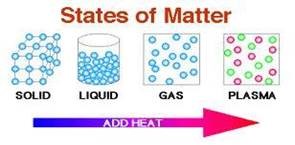 Air, water, automobiles, clothing, and even our bodies are examples of matter. Thus, we may find matter in any one of four states:
Elements, Compounds, and Mixtures
Elements
An element is a substance that cannot be reduced to a simpler substance by chemical means.
Examples of elements you are in regular contact with are iron, gold, silver, copper, and oxygen.
There are now over 100 known elements. All the different substances we know about are composed of one or more of these elements. The resulting substance is called a compound when two or more elements are chemically combined.
Compounds

A compound is a chemical combination of elements that can be separated by chemicals but not by physical means.
Examples of common compounds are water, which consists of hydrogen and oxygen, and table salt, which consists of sodium and chlorine.

Mixtures
On the other hand, a mixture is a combination of elements and compounds, not chemically combined, that can be separated by physical means.
Examples of mixtures are air, which is made up of nitrogen, oxygen, carbon dioxide, & small amounts of several rare gases, & seawater.
Molecules
A molecule combines two or more atoms (atoms to be described shortly) in a compound. The molecule is the smallest particle with all the compound’s characteristics.
For example. Water is matter since it occupies space and has weight.
Depending on the temperature, it may exist as;
- a liquid (water),
- a solid (ice), or;
- a gas (steam).
Regardless of the temperature, it will still have the same composition.
If we start with a quantity of water, divide this pour out one half, and continue this process a sufficient number of times, we will eventually end up with a quantity of water that cannot be further divided without ceasing to be water.
This quantity is called a molecule of water.
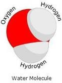
If this molecule of water is divided, instead of two parts of water, there will be one part of oxygen and two parts of hydrogen (H2O).
Molecules are made up of smaller particles called atoms.
Atoms
An atom is the smallest particle of an element that retains the characteristics of that element. However, the atoms of one element differ from the atoms of all other elements.
Since there are over 100 known elements, there must be over 100 different atoms or a different atom for each element. Just as thousands of words can be made by combining the proper letters of the alphabet, thousands of different materials can be made by chemically combining the correct atoms.
Any particle that is a chemical combination of two or more atoms is called a molecule.
- The oxygen molecule consists of two atoms of oxygen, and
- The hydrogen molecule consists of two atoms of hydrogen.
Sugar, on the other hand, is a compound composed of atoms of carbon, hydrogen, and oxygen, and these atoms are combined into sugar molecules. Since the sugar molecules can be broken down by chemical means into smaller and simpler units, we cannot have sugar atoms.
Electrons, Protons & Neutrons

The atoms of each element are made up of electrons, protons, and, in most cases, neutrons, which are collectively called subatomic particles. Furthermore, one element’s electrons, protons, and neutrons are identical to those of any other element.
There are different kinds of elements because the number and the arrangement of electrons and protons within the atom are different for the different elements.
The electron is considered to be a small negative charge of electricity. The proton has a positive charge of electricity equal to and opposite to the charge of the electron. Scientists have measured the mass and size of the electron and proton, and they know how much charge each possesses.
The electron and proton each have the same amount of charge, although the proton’s mass is approximately 1837 times that of the electron. In some atoms, there exists a neutral particle called a neutron.
The neutron has a mass approximately equal to that of a proton, but it has no electrical charge. According to a popular theory, the atoms’ electrons, protons, and neutrons are thought to be arranged like a miniature solar system.
The protons & neutrons form a heavy nucleus with a positive charge, around which the very light electrons revolve. Each has a relatively simple structure.
The diagram below shows one hydrogen and one helium atom.
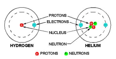
The hydrogen atom has only one proton in the nucleus with one electron rotating about it.
The helium atom is a little more complex, and it has a nucleus made up of two protons and two neutrons, with two electrons rotating about the nucleus.
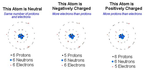
Elements are classified numerically according to the complexity of their atoms. The atomic number of an atom is determined by the number of protons in its nucleus. In a neutral state, an atom contains an equal number of protons and electrons.
Therefore, an atom of hydrogen – which contains one proton and one electron—has an atomic number of 1; and helium, with two protons and two electrons, has an atomic number of 2. The complexity of atomic structure increases with the number of protons and electrons.
Energy Levels
Since an electron in an atom has both mass and motion, it contains two types of energy.
- By virtue of its motion, the electron contains Kinetic Energy.
- Due to its position, it also contains Potential Energy.
The total energy contained by an electron (kinetic plus potential) is the factor that determines the radius of the electron orbit. An electron must neither gain nor lose energy to remain in this orbit.
It is well known that light is a form of energy, but the physical form in which this energy exists is not known. One accepted theory proposes the existence of light as tiny packets of energy called photons.
Photons can contain various quantities of energy, and the amount depends upon the color of the light involved.
 Should a photon of sufficient energy collide with an orbital electron, the electron will absorb the photon’s energy, as shown in the figure to the right.
The electron, which now has a greater-than-normal amount of energy, will jump to a new orbit farther from the nucleus. The first new orbit to which the electron can jump has a radius four times as large as the radius of the original orbit.
Had the electron received a greater amount of energy, the next possible orbit to which it could jump would have a radius nine times the original. Thus, each orbit may be considered to represent one of a large number of energy levels that the electron may attain.
It must be emphasized that the electron cannot jump to just any orbit. The electron will remain in its lowest orbit until a sufficient amount of energy is available, at which time the electron will accept the energy and jump to one of a series of permissible orbits.
An electron cannot exist in the space between energy levels. This indicates that the electron will not accept a photon of energy unless it contains enough energy to elevate itself to one of the higher energy levels.
Heat energy and collisions with other particles can also cause the electron to jump orbits. Once the electron has been elevated to an energy level higher than the lowest possible energy level, the atom is said to be in an excited state. The electron will not remain in this excited condition for more than a fraction of a second before radiating the excess energy and returning to a lower energy orbit.
To illustrate this principle, assume that a normal electron has just received a photon of energy sufficient to raise it from the first to the third energy level. The electron may jump back to the first level in a short period, emitting a new photon identical to the one it received.
A second alternative would be for the electron to return to the lower level in two jumps: from the third to the second and then from the second to the first. In this case, the electron would emit two photons, one for each jump. Each of these photons would have less energy than the original photon, which excited the electron.
This principle is used in fluorescent light, where ultraviolet light photons, which are not visible to the human eye, bombard a phosphor coating on the inside of a glass tube. In returning to their regular orbits, the phosphor electrons emit visible photons of light.
Using the proper chemicals for the phosphor coating, any color of light may be obtained, including white. This same principle is also used in lighting up the screen of a television picture tube.
The basic principles just developed apply equally well to the atoms of more complex elements. In atoms containing two or more electrons, the electrons interact with each other, and the exact path of any one electron is challenging to predict. However, each electron lies in a specific energy band, and the orbits will be considered as an average of the electron’s position.
Valence
The number of electrons in the outermost shell determines the valence of an atom. For this reason, the outer shell of an atom is called the valence shell, and the electrons contained in this shell are called valence electrons.
The valence of an atom determines its ability to gain or lose an electron, which determines the atom’s chemical and electrical properties. An atom that lacks only one or two electrons from its outer shell will easily gain electrons to complete its shell, but a large amount of energy is required to free any of its electrons.
An atom with a relatively small number of electrons in its outer shell compared to the number of electrons required to fill the shell will easily lose these valence electrons. The valence shell always refers to the outermost shell.
Ionization
An ion is a charged atom or molecule, and it is charged because the number of electrons does not equal the number of protons in the atom or molecule. When the atom loses electrons or gains electrons in this electron exchange process, it is said to be ionized.
For ionization to take place, there must be a transfer of energy, which results in a change in the internal energy of the atom. An atom with more than its normal amount of electrons acquires a negative charge called a negative ion.
The atom that gives up some of its normal electrons is left with fewer negative charges than positive charges and is called a positive ion.
Thus, ionization is the process by which an atom loses or gains electrons.
Conductors, Insulators, and Semiconductors
In this study of electricity, the association of matter and electricity is important. Since every electronic device is constructed of parts made from ordinary matter, the effects of electricity on matter must be well understood.
All elements of which matter is made may be placed into one of three categories: Conductors, insulators, and semiconductors, depending on their ability to conduct an electric current.
- Conductors are elements that conduct electricity very readily,
- Insulators have an extremely high resistance to the flow of electricity.
- All matter between these two extremes may be called Semiconductors.
The electron theory states that all matter is composed of atoms, and the atoms are composed of smaller particles called protons, electrons, and neutrons. The electrons orbit the nucleus, which contains the protons and neutrons.
It is the valence electrons that we are most concerned with regarding electricity. These are the easiest electrons to break loose from their parent atom. Normally, conductors have three or fewer valence electrons; insulators have five or more valence electrons, and semiconductors usually have four valence electrons.
The electrical conductivity of matter is dependent upon the atomic structure of the material from which the conductor is made. In any solid material, such as copper, the atoms that make up the molecular structure are bound firmly together.
At room temperature, copper will contain a considerable amount of heat energy. Since heat energy is one method of removing electrons from their orbits, copper will contain many free electrons that can move from atom to atom.
When not under the influence of an external force, these electrons move haphazardly within the conductor. This movement is equal in all directions so that electrons are not lost or gained by any part of the conductor.
When controlled by an external force, the electrons generally move in the same direction. The effect of this movement is felt almost instantly from one end of the conductor to the other. This electron movement is called an Electric Current.
Some metals are better conductors of electricity than others. Silver, copper, gold, and aluminum are materials with many free electrons and make good conductors. Silver is the best conductor, followed by copper, gold, and aluminum.
- Copper is used more often than silver because of cost.
- Aluminum is used where weight is a major consideration, such as in high-tension power lines with long spans between supports.
- Silver is the best conductor, but it is expensive and oxidizes easily,
- Gold is used where oxidation or corrosion is a consideration, and good conductivity is required.
The ability of a conductor to handle current also depends upon its physical dimensions. Conductors are usually found in the form of wire but may be in the form of bars, tubes, or sheets.
Nonconductors have few free electrons. These materials are called Insulators. Some examples of these materials are rubber, plastic, enamel, glass, dry wood, and mica. Just as there is no perfect conductor, neither is there a perfect insulator.
Some materials are neither good conductors nor good insulators since their electrical characteristics fall between those of conductors and insulators. These in-between materials are classified as Semiconductors. Germanium and silicon are two common semiconductors used in solid-state devices.
Electrostatics
Electrostatics (electricity at rest) is a subject with which most persons entering the field of electricity are somewhat familiar.
For example, the way a person’s hair stands on end after a vigorous rubbing is an effect of electrostatics. While pursuing the study of electrostatics, you will gain a better understanding of this common occurrence.
Of even greater significance, the study of electrostatics will provide you with the opportunity to gain important background knowledge and to develop concepts that are essential to the understanding of electricity.
Interest in the subject of static electricity can be traced back to the Greeks.

Thales of Miletus, a Greek philosopher and mathematician, discovered that when an amber rod is rubbed with fur, the rod has the amazing characteristic of attracting some very light objects, such as bits of paper and shavings of wood.

In about 1600, William Gilbert, an English scientist, made a study of other substances that had been found to possess qualities of attraction similar to amber. Among these were glass, when rubbed with silk, and ebonite, when rubbed with fur.
Gilbert classified all the substances that possessed properties similar to those of amber as electrics, a word of Greek origin meaning amber. Because of Gilbert’s work with electrics, a substance such as amber or glass was recognized as being electrified or charged with electricity when given vigorous rubbing.

In the year 1733, Charles Dufay, a French scientist, made an important discovery about electrification.
He found that when a glass was rubbed with fur, both the glass rod and the fur became electrified. This realization came when he systematically placed the glass rod and the fur near other electrified substances and found that certain substances that were attracted to the glass rod were repelled by the fur and vice versa. He concluded from experiments such as this that there must be two exactly opposite kinds of electricity.

Benjamin Franklin, an American statesman, inventor, and philosopher, is credited with first using the terms positive and negative to describe the two opposite kinds of electricity.
The charge produced on a glass rod when it is rubbed with silk, Franklin labeled positive. He attached the term negative to the charge produced on the silk. Those bodies which were not electrified or charged, he called neutral.
Static Electricity
In a natural or neutral state, each atom in a body of matter will have the proper number of electrons in orbit around it. Consequently, the whole body of matter composed of neutral atoms will also be electrically neutral. In this state, it is said to have a “zero charge.”
Electrons will neither leave nor enter the neutrally charged body should they come in contact with other neutral bodies. If any number of electrons are removed from the atoms of a body of matter, there will remain more protons than electrons, and the whole body of matter will become electrically positive.
If the positively charged body comes in contact with another body having a normal or negative (too many electrons) charge, an electric current will flow between them.
Electrons will leave the more negative body and enter the positive body. This electron flow will continue until both bodies have equal charges.
When two bodies of matter have unequal charges and are near one another, an electric force is exerted between them because of their unequal charges. However, since they are not in contact, their charges cannot equalize.
The existence of such an electric force, where current cannot flow, is referred to as static electricity. (“Static” in this instance means “not moving.”) It is also referred to as an electrostatic force.
One of the easiest ways to create a static charge is by friction. When two pieces of matter are rubbed together, electrons can be “wiped off” one material onto the other. If the materials used are good conductors, obtaining a detectable charge on either is difficult since equalizing currents can flow easily between the conducting materials.
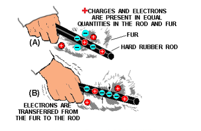
These currents equalize the charges almost as fast as they are created. A static charge is more easily created between non-conducting materials. When a hard rubber rod is rubbed with fur, the rod will accumulate electrons given up by the fur, as shown in below.
Reaction Between Charged Bodies
Since both materials are poor conductors, very little equalizing current can flow, and an electrostatic charge builds up. When the charge becomes great enough, the current will flow regardless of the poor conductivity of the materials. These currents will cause visible sparks and produce a crackling sound.
Nature of Charges
When in a natural or neutral state, an atom has an equal number of electrons and protons. Because of this balance, the net negative charge of the electrons in orbit is exactly balanced by the net positive charge of the protons in the nucleus, making the atom electrically neutral.
An atom becomes a positive ion whenever it loses an electron and has an overall positive charge. Conversely, whenever an atom acquires an extra electron, it becomes a negative ion and has a negative charge.
Due to normal molecular activity, there are always ions present in any material.
- The material is electrically neutral if the number of positive and negative ions is equal.
- The material is positively charged when the number of positive ions exceeds the number of negative ions.
- The material is negatively charged whenever the negative ions outnumber the positive ions.
Since ions are atoms without their normal number of electrons, a substance’s excess or lack of electrons determines its charge.
In most solids, the transfer of charges is by the movement of electrons rather than ions. The transfer of charges by ions will become more significant when we consider electrical activity in liquids and gases. At this time, we will discuss electrical behavior in terms of electron movement.
Charged Bodies
One of the fundamental laws of electricity is that like charges repel each other, and unlike charges attract each other. A positive charge and a negative charge, being unlike, tend to move toward each other. In the atom, the negative electrons are drawn toward the positive protons in the nucleus. This attractive force is balanced by the electron’s centrifugal force caused by its rotation about the nucleus. As a result, the electrons remain in orbit and are not drawn into the nucleus.
Electrons repel each other because of their like negative charges, and protons repel each other because of their like positive charges. The law of charged bodies may be demonstrated by a simple experiment. Two pith (paper pulp) balls are suspended near one another by threads, as shown below.

If a hard rubber rod is rubbed with fur to give it a negative charge and is then held against the right-hand ball in part (A), the rod will give off a negative charge to the ball. The right-hand ball will have a negative charge with respect to the left-hand ball. The two balls will be drawn together when released, as shown (A).
They will touch and remain in contact until the left-hand ball gains a portion of the negative charge of the right-hand ball, at which time they will swing apart, as shown in (C). If a positive or a negative charge is placed on both balls (B), the balls will repel each other.

Coulomb’s Law of Charges
Coulomb’s law or Coulomb’s inverse-square law is a law of physics describing the electrostatic interaction between electrically charged particles. It was first published in 1785 by French physicist Charles Augustin de Coulomb and was essential to the development of the theory of electromagnetism.
This law states, “The force of attraction or repulsion between two point charges is directly proportional to the product of the magnitude of each charge and indirectly proportional to the square of the distance between them.”
Charged bodies attract or repel each other with a force directly proportional to the product of their individual charges and inversely proportional to the square of the distance between them.

The amount of attracting or repelling force that acts between two electrically charged bodies in free space depends on two things:
-
- Their charges and
- The distance between them.
Electric Fields
The space between and around charged bodies in which their influence is felt is called an Electric Field of Force. It can exist in air, glass, paper, or a vacuum. Electrostatic Fields and Dielectric Fields are other names used to refer to this region of force.
Fields of force spread out in the space surrounding their point of origin and generally diminish in proportion to the square of the distance from their source. The field about a charged body is generally represented by lines, which are referred to as Electrostatic Lines of Force.
These lines are imaginary and are used merely to represent the direction and strength of the field. To avoid confusion, the lines of force exerted by a positive charge are always shown leaving the charge, and for a negative charge, they are shown entering.
The image below illustrates the use of lines to represent the field of charged bodies.

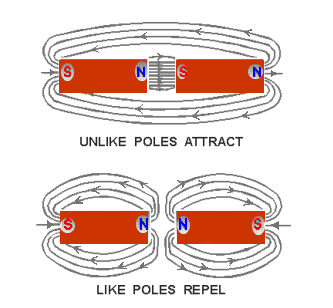
Electrostatic Lines of Force
Part (A) represents the repulsion of like-charged bodies and their associated fields.
Part (B) represents the attraction of unlike-charged bodies and their associated fields.
Magnetism
In order to properly understand the principles of electricity, it is necessary to study magnetism and the effects of magnetism on electrical equipment. Magnetism and electricity are so closely related that the study of either subject would be incomplete without at least a basic knowledge of the other.
Much of today’s modern electrical and electronic equipment could not function without magnetism.
- Modern computers, audio, and video equipment use magnetized components.
- High-fidelity speakers use magnets to convert amplifier outputs into audible sound.
- Electrical motors use magnets to convert electrical energy into mechanical motion; generators use magnets to convert mechanical motion into electrical energy.
Magnetic Material
Magnetism is generally defined as the property of a material that enables it to attract pieces of iron. A material possessing this property is known as a magnet. The word originated with the ancient Greeks, who found stones possessing this characteristic.
Materials that are attracted by a magnet, such as iron, steel, nickel, and cobalt, have the ability to become magnetized. These are called magnetic materials.
Materials such as paper, wood, glass, or tin, which are not attracted by magnets, are considered nonmagnetic. Nonmagnetic materials are not able to become magnetized.
Ferromagnetic Materials
The most important group of materials connected with electricity and electronics are ferromagnetic materials. Ferromagnetic materials are those that are relatively easy to magnetize, such as iron, steel, cobalt, and the alloys Alnico and Permalloy. (An alloy is made by combining two or more elements, one of which must be metal).
These new alloys can be very strongly magnetized and are capable of obtaining a magnetic strength great enough to lift 500 times their own weight.
Natural Magnets
Magnetic stones such as those found by the ancient Greeks are considered to be natural magnets. These stones had the ability to attract small pieces of iron in a manner similar to the magnets that are common today.

However, the magnetic properties attributed to the stones were products of nature and not the result of the efforts of man. The Greeks called these substances magnetite.
The Chinese are said to have been aware of some of the effects of magnetism as early as 2600 B.C. They observed that stones similar to magnetite, when freely suspended, had a tendency to assume a nearly north and south direction. Because of the directional quality of these stones, they were later referred to as lodestones or leading stones.
Natural magnets, which presently can be found in the United States, Norway, and Sweden, no longer have any practical use, for it is now possible to easily produce more powerful magnets.
Artificial Magnets
Magnets produced from magnetic materials are called artificial magnets. They can be made in a variety of shapes and sizes and are used extensively in electrical apparatus.
Artificial magnets are generally made from special iron or steel alloys, which are usually magnetized electrically. The material to be magnetized is inserted into a coil of insulated wire, and a heavy flow of electrons is passed through the wire.
Magnets can also be produced by stroking a magnetic material with magnetite or with another artificial magnet. Magnetic lines of force represent the forces causing magnetization, which are very similar in nature to electrostatic lines of force.
Artificial magnets are usually classified as permanent or temporary, depending on their ability to retain their magnetic properties after removing the magnetizing force. Magnets made from substances, such as hardened steel and certain alloys that retain a great deal of their magnetism, are called permanent magnets.
These materials are relatively difficult to magnetize because of the opposition offered to the magnetic lines of force as the lines of force try to distribute themselves throughout the material. A material’s opposition to the magnetic lines of force is called reluctance. All permanent magnets are produced from materials having a high reluctance.
A material with a low reluctance, such as soft iron or annealed silicon steel, is relatively easy to magnetize but will retain only a small part of its magnetism once the magnetizing force is removed. Materials of this type that easily lose most of their magnetic strength are called temporary magnets.
The amount of magnetism that remains in a temporary magnet is referred to as its residual magnetism. The ability of a material to retain an amount of residual magnetism is called the retentivity of the material.
The difference between a permanent and a temporary magnet has been indicated in reluctance, a permanent magnet with a high reluctance and a temporary magnet with a low reluctance.
Magnets are also described in terms of the permeability of their materials or the ease with which magnetic lines of force distribute themselves throughout the material.
- A permanent magnet, which is produced from a material with a high reluctance, has a low permeability.
- A temporary magnet, produced from a material with a low reluctance, would have a high permeability.
Magnetic Poles
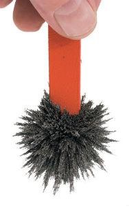
The magnetic force surrounding a magnet is not uniform. A great concentration of force exists at each end of the magnet and a very weak force at the center. Proof of this fact can be obtained by dipping a magnet into iron filings.
It is found that many filings will cling to the ends of the magnet while very few adhere to the center. The two ends, which are the regions of concentrated lines of force, are called the poles of the magnet.
Magnets have two magnetic poles, and both poles have equal magnetic strength.
Law of Magnetic Poles
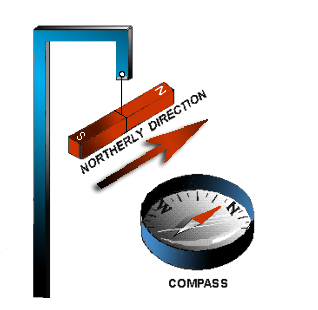 If a bar magnet is suspended freely on a string, as shown in the figure to the left, it will align itself in a north and south direction.
When this experiment is repeated, it is found that the same pole of the magnet will always swing toward the earth’s north magnetic pole. Therefore, it is called the North-seeking Pole or simply the North Pole. The other pole of the magnet is the south-seeking pole or the South Pole.
A practical use of the directional characteristic of the magnet is the compass, a device in which a freely rotating magnetized needle indicator points toward the North Pole. The realization that the poles of a suspended magnet always move to a definite position gives an indication that the opposite poles of a magnet have opposite magnetic polarity.
The law previously stated regarding the attraction and repulsion of charged bodies may also be applied to magnetism if the pole is considered as a charge. The north pole of a magnet will always be attracted to the south pole of another magnet and will show repulsion to the north pole. The law for magnetic poles is: As like poles repel, unlike poles attract.
The Earth’s Magnetic Poles
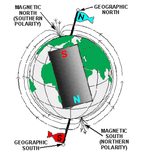
The fact that a compass needle always aligns itself in a particular direction, regardless of its location on Earth, indicates that the earth is a huge natural magnet. The magnetic force distribution about the Earth is the same as that which might be produced by a giant bar magnet running through the center of the Earth in the figure to the right.
The earth’s magnetic axis is located about 15(0) 15 from its geographical axis, thereby locating the magnetic poles some distance from the geographical poles. The ability of the compass needle’s north pole to point toward the north geographical pole is due to the magnetic pole nearby. This magnetic pole is named the Magnetic North.
However, it must have the polarity of a south magnetic pole since it attracts the north pole of a compass needle. The reason for this conflict in terminology can be traced to the early users of the compass. Knowing little about magnetic effects, they called the end of the compass needle that pointed towards the north geographical pole the north pole of a compass.
With our present knowledge of magnetism, we know the north pole of a compass needle (a small bar magnet) can be attracted only by an unlike magnetic pole, a pole of south magnetic polarity.
Theories of Magnetism
Webster’s Theory
A popular theory of magnetism considers the molecular alignment of the material.
 Wilhelm Eduard Weber, (Oct. 24, 1804, to June 23, 1891, German physicist who, with his friend Carl Friedrich Gauss, investigated terrestrial magnetism and in 1833, devised an electromagnetic telegraph. The magnetic unit, termed a Weber, formerly the Coulomb, is named after him. This theory assumes that all magnetic substances are composed of tiny molecular magnets.
Any unmagnetized material has the magnetic forces of its molecular magnets neutralized by adjacent molecular magnets, thereby eliminating any magnetic effect. A magnetized material will have most of its molecular magnets lined up so that the north pole of each molecule points in one direction, and the south pole faces the opposite direction. A material with its molecules thus aligned will then have one effective north pole and one effective south pole.
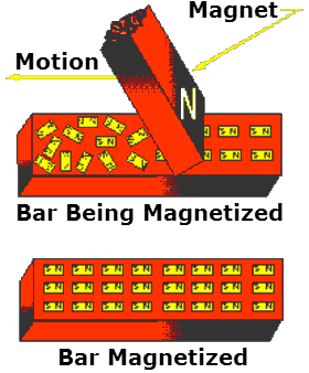
An illustration of Weber’s Theory is shown to the right, where a steel bar is magnetized by stroking.
When a steel bar is stroked several times in the same direction by a magnet, the magnetic force from the magnet’s north pole causes the molecules to align themselves.
Domains Theory
A more modern theory of magnetism is based on the electron spin principle. From the study of atomic structure, it is known that all matter is composed of vast quantities of atoms, each atom containing one or more orbital electrons.
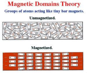
The domain theory states that inside a magnet, there are small regions in which the magnetic direction of all the atoms is aligned in the same direction. These regions are known as domains.
Within a domain, the alignment of the magnetic direction is the same. In the next domain, it may be in a completely different direction.
On average, over the many domains in the magnet, there is no preferential direction for the magnetic force. However, using an external magnetic field from another magnet, the magnetic direction in each domain can be made to align with the magnetic field the net magnetic field can be increased.
The electrons are considered to orbit in various shells and subshells depending upon their distance from the nucleus. The structure of the atom has previously been compared to the solar system, wherein the electrons orbiting the nucleus correspond to the planets orbiting the sun. Along with its orbital motion about the sun, each planet also revolves on its axis. It is believed that the electron also revolves on its axis as it orbits the nucleus of an atom.
It has been experimentally proven that an electron has a magnetic field about it along with an electric field. The effectiveness of the magnetic field of an atom is determined by the number of electrons spinning in each direction.
If an atom has equal numbers of electrons spinning in opposite directions, the magnetic fields surrounding the electrons cancel one another, and the atom is unmagnetized. However, if more electrons spin in one direction than another, the atom is magnetized.
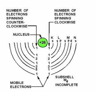
An atom with an atomic number of 26, such as iron, has 26 protons in the nucleus and 26 revolving electrons orbiting its nucleus. If 13 electrons spin in a clockwise direction and 13 spin in a counterclockwise direction, the opposing magnetic fields will be neutralized.
The atom is magnetized when more than 13 electrons spin in either direction. An example of a magnetized atom of iron is shown below.
Magnetic Fields
The space surrounding a magnet where magnetic forces act is known as the magnetic field.
A pattern of this directional force can be obtained by performing an experiment with iron filings. A piece of glass is placed over a bar magnet, and the iron filings are sprinkled on the glass’s surface.
The magnetizing force of the magnet will be felt through the glass, and each iron filing becomes a temporary magnet. If the glass is now tapped gently, the iron particles will align themselves with the magnetic field surrounding the magnet just as the compass needle did previously.
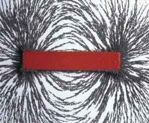
The filings form a definite pattern, which is a visible representation of the forces comprising the magnetic field. Examination of the arrangements of iron filings in will indicate that the magnetic field is very strong at the poles and weakens as the distance from the poles increases. It is also apparent that the magnetic field extends from one pole to the other, constituting a loop about the magnet.
Lines of Force
To further describe and work with magnet phenomena, lines are used to represent the force existing in the area surrounding a magnet.

These lines, called Magnetic Lines of Force, do not actually exist but are imaginary lines used to illustrate and describe the pattern of the magnetic field. The magnetic lines of force are assumed to emanate from the north pole of a magnet, pass through surrounding space, and enter the south pole. The lines of force travel inside the magnet from the south pole to the north pole, thus completing a closed loop.
When two magnetic poles are brought close together, the mutual attraction or repulsion of the poles produces a more complicated pattern than that of a single magnet. These magnetic lines of force can be plotted by placing a compass at various points throughout the magnetic field, or they can be roughly illustrated by the use of iron filings as before.
The image to the left shows a diagram of magnetic poles placed close together.
Although magnetic lines of force are imaginary, a simplified version of many magnetic phenomena can be explained by assuming the magnetic lines to have certain real properties. The lines of force can be compared to rubber bands that stretch outward when a force is exerted upon them and contract when the force is removed.
The characteristics of magnetic lines of force can be described as follows:
- Magnetic lines of force are continuous and will always form closed loops.
- Magnetic lines of force will never cross one another.
- Parallel magnetic lines of force traveling in the same direction repel one another.
- Parallel magnetic lines of force traveling in opposite directions tend to unite with each other and form into single lines traveling in a direction determined by the magnetic poles creating the lines of force.
- Magnetic lines of force tend to shorten themselves. Therefore, the magnetic lines of force existing between two unlike poles cause the poles to be pulled together.
- Magnetic lines of force pass through all materials, both magnetic and nonmagnetic.
- Magnetic lines of force always enter or leave a magnetic material at right angles to the surface.
Magnetic Effects
Magnetic Flux. The total number of magnetic lines of force leaving or entering the pole of a magnet is called Magnetic Flux. The number of flux lines per unit area is known as Flux Density.
Field Intensity. The intensity of a magnetic field is directly related to the magnetic force exerted by the field.
Attraction/Repulsion. The intensity of attraction or repulsion between magnetic poles may be described by a law almost identical to Coulomb’s Law of Charged Bodies. The force between two poles is directly proportional to the product of the pole strengths and inversely proportional to the square of the distance between the poles.
Magnetic Induction
It has been previously stated that all substances that are attracted by a magnet are capable of becoming magnetized. The fact that a material is attracted by a magnet indicates the material must itself be a magnet at the time of attraction.
With the knowledge of magnetic fields and magnetic lines of force developed up to this point, it is simple to understand the manner in which a material becomes magnetized when brought near a magnet.
As an iron nail is brought close to a bar magnet, some flux lines emanating from the magnet’s north pole pass through the iron nail in completing their magnetic path.
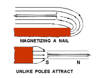 Since magnetic lines of force travel inside a magnet from the south pole to the north pole, the nail will be magnetized in such a polarity that its south pole will be adjacent to the north pole of the bar magnet.
There is now an attraction between the two magnets. If another nail is brought in contact with the end of the first nail, it would be magnetized by induction.
This process could be repeated until the strength of the magnetic flux weakens as the distance from the bar magnet increases. However, as soon as the first iron nail is pulled away from the bar magnet, all the nails will fall. The reason is that each nail becomes a temporary magnet, and as soon as the magnetizing force is removed, their domains once again assume a random distribution.
Magnetic induction will always produce a pole polarity on the material being magnetized opposite that of the adjacent pole of the magnetizing force. It is sometimes possible to bring a weak north pole of a magnet near a strong magnet north pole and note attraction between the poles.
When placed within the magnetic field of the strong magnet, the weak magnet has its magnetic polarity reversed by the field of the stronger magnet. Therefore, it is attracted to the opposite pole.
For this reason, you must keep a very weak magnet, such as a compass needle, away from a strong magnet.
Magnetism can be induced in a magnetic material by several means.
The magnetic material may be placed in the magnetic field, brought into contact with a magnet, or stroked by a magnet. Stroking and contact both indicate actual contact with the material but are considered in magnetic studies as magnetizing by induction.
Magnetic Shielding
There is no known Insulator for magnetic flux. If a nonmagnetic material is placed in a magnetic field, there is no appreciable change in flux – that is, the flux penetrates the nonmagnetic material.

For example, a glass plate placed between the poles of a horseshoe magnet will have no appreciable effect on the field although glass itself is a good insulator in an electric circuit. If a magnetic material (For example, soft iron) is placed in a magnetic field, the flux may be redirected to take advantage of the greater permeability of the magnetic material.
Permeability, as discussed earlier, is the quality of a substance that determines the ease with which it can be magnetized. The sensitive mechanisms of electric instruments and meters can be influenced by stray magnetic fields, which will cause errors in their readings.

Because instrument mechanisms cannot be insulated against magnetic flux, it is necessary to employ some means of directing the flux around the instrument. This is accomplished by placing a soft-iron case, called a Magnetic Screen or Shield, on the instrument.
Because the flux is established more readily through the iron (even though the path is longer) than through the air inside the case, the instrument is effectively shielded, as shown by the watch and soft iron shield.
Magnetic Shapes
Because of the many uses of magnets, they are found in various shapes and sizes.
However, magnets usually come under one of three general classifications:
- Bar magnets,
- Ring magnets, or
- Horseshoe magnets.
The bar magnet is most often used in schools and laboratories to study magnetism’s properties and effects. In the preceding material, the bar magnet proved very helpful in demonstrating magnetic effects.
Another type of magnet is the ring magnet, which is used for computer memory cores. A common application for a temporary ring magnet would be the shielding of electrical instruments.
The shape of the magnet most frequently used in electrical and electronic equipment is called the horseshoe magnet. A horseshoe magnet is similar to a bar magnet but is bent in the shape of a horseshoe.
The horseshoe magnet provides much more magnetic strength than a bar magnet of the same size and material because of the closeness of the magnetic poles. The magnetic strength from one pole to the other is greatly increased due to the concentration of the magnetic field in a smaller area. Electrical measuring devices quite frequently use horseshoe-type magnets.
Care of Magnets
A piece of steel that has been magnetized can lose much of its magnetism by improper handling. If it is jarred or heated, there will be a dis-alignment of its domains, resulting in the loss of some of its effective magnetism.
Had this piece of steel formed the horseshoe magnet of a meter, the meter would no longer be operable or would give inaccurate readings. Therefore, care must be exercised when handling instruments containing magnets. Severe jarring or subjecting the instrument to high temperatures will damage the device.
A magnet may also become weakened from loss of flux. Thus, when storing magnets, one should always try to avoid excessive leakage of magnetic flux.
A horseshoe magnet should always be stored with a keeper, a soft iron bar used to join the magnetic poles. Using the keeper while the magnet is being stored, the magnetic flux will continuously circulate through the magnet and not leak into space. When bar magnets are stored, the same principle must be remembered.
Therefore, bar magnets should always be stored in pairs with a north pole and a south pole placed together. This provides a complete path for the magnetic flux without any flux leakage.
Electrical Energy
In the field of physical science, work must be defined as the Product of Force and Displacement. The force applied to move an object, and the distance the object is moved are the factors of work performed.
It is important to notice that no work is accomplished unless the force applied causes a change in the position of a stationary object or a change in the velocity of a moving object. A worker may tire by pushing against a heavy wooden crate, but no work will be accomplished unless the crate moves.
Energy
We must define energy as The Ability to Do Work in our study of energy and work. In order to perform any kind of work, energy must be expended (converted from one form to another). Energy supplies the required force, or power, whenever any work is accomplished.
One form of energy is that which is contained by an object in motion.
When a hammer is set in motion in the direction of a nail, it possesses an energy of motion. As the hammer strikes the nail, the energy of motion is converted into work as the nail is driven into the wood. The distance the nail is driven into the wood depends on the velocity of the hammer at the time it strikes the nail.
Kinetic Energy is The energy an object contains due to its motion.
Assume that the hammer is suspended by a string in a position one meter above a nail. As a result of gravitational attraction, the hammer will experience a force pulling it downward. If the string is suddenly cut, the force of gravity will pull the hammer down against the nail, driving it into the wood.
While the hammer is suspended above the nail, it can do work because of its elevated position in the earth’s gravitational field. Since energy is the ability to do work, the hammer contains energy.
The energy contained by an object due to its position is called Potential Energy.
The amount of potential energy available is equal to the product of the force required to elevate the hammer and the height to which it is elevated.
Another example of potential energy is that contained in a tightly coiled spring. The energy released when the spring unwinds depends on the initial force required to wind the spring.
Electrical Charges
From the previous study of electrostatics, you learned that a field of force exists in the space surrounding any electrical charge. The strength of the field is directly dependent on the force of the charge.
The charge of one electron might be used as a unit of electrical charge since charges are created by the displacement of electrons, but the charge of one electron is so small that it is impractical to use. The practical unit adopted for measuring charges is the Coulomb, named after the scientist Charles Coulomb.
One coulomb is equal to the charge of 6,280,000,000,000,000,000 (six quintillion two hundred and eighty quadrillion) or (6.28 x 10)(18) electrons when a charge of one coulomb exists between two bodies, one unit of electrical potential energy exists, which is called the difference of potential between the two bodies. This is referred to as Electromotive Force or Voltage, and the unit of measure is the Volt
Electrical charges are created by the displacement of electrons so that an excess of electrons exists at one point and a deficiency at another point. Consequently, a charge must always have either a negative or positive polarity.
A body with an excess of electrons is considered to be negative, whereas a body with a deficiency of electrons is positive. A difference of potential can exist between two points or bodies only if they have different charges. In other words, there is no difference in potential between two bodies if both have a deficiency of electrons to the same degree.
If, however, one body is deficient by 6 coulombs (representing 6 volts), and the other is deficient by 12 coulombs (representing 12 volts), there is a difference of potential of 6 volts. The body with the greater deficiency is positive with respect to the other. In most electrical circuits, only the difference in potential between two points is of importance, and the absolute potentials of the points are of little concern.
Very often, using one standard reference for all of the various potentials throughout a piece of equipment is convenient. For this reason, the potentials at various points in a circuit are generally measured with respect to the metal chassis on which all parts of the circuit are mounted. The chassis is considered to be at zero potential, and all other potentials are either positive or negative with respect to the chassis.
When used as the reference point, the chassis is said to be at Ground Potential.
Occasionally, rather large values of voltage may be encountered, in which case the volt becomes too small a unit for convenience. In a situation of this nature, the kilovolt (kV), meaning 1,000 volts, is frequently used. As an example, 20,000 volts would be written as 20 kV.
In other cases, the volt may be too large a unit, as when dealing with very small voltages. For this purpose, the millivolt (mV), meaning one-thousandth of a volt, and the microvolt(µV), meaning one-millionth of a volt, are used.
For example,
- 0.001 volts would be written as one mV,
- 0.000025 volts would be written as 25 (µV)
When a difference in potential exists between two charged bodies that are connected by a conductor, electrons will flow along the conductor. This flow is from the negatively charged body to the positively charged body until the two charges are equalized, and the potential difference no longer exists.
An analogy of this action is shown below in the two water tanks connected by a pipe and valve.

At first, the valve is closed, and all the water is in tank A. Thus, the water pressure across the valve is at maximum. When the valve is opened, the water flows through the pipe from A to B until the water level becomes the same in both tanks. The water then stops flowing in the pipe because there is no longer a difference in water pressure between the two tanks.
Electron movement through an electric circuit is directly proportional to the difference in potential or electromotive force (emf) across the circuit, just as the flow of water through the pipe above, and is directly proportional to the difference in water level in the two tanks.
A fundamental law of electricity is that The Electron Flow Is Directly Proportional to The Applied Voltage.
- If the voltage is increased, the flow is increased.
- If the voltage is decreased, the flow is decreased.
How Voltage Is Produced
It has been demonstrated that a charge can be produced by rubbing a rubber rod with fur. Because of the friction involved, the rod acquires electrons from the fur, making it negative; the fur becomes positive due to the loss of electrons. These quantities of charge constitute a difference of potential between the rod and the fur. The electrons that make up this difference of potential are capable of doing work if a discharge is allowed to occur.
To be a practical source of voltage, the potential difference must not be allowed to dissipate but must be maintained continuously. As one electron leaves the concentration of negative charge, another must be immediately provided to take its place, or the charge will eventually diminish to the point where no further work can be accomplished.
A voltage source, therefore, is a device that is capable of supplying and maintaining voltage while some type of electrical apparatus is connected to its terminals.
The internal action of the source is such that electrons are continuously removed from one terminal, keeping it positive, and simultaneously supplied to the second terminal, which maintains a negative charge.
Six known methods exist for producing a voltage or electromotive force (emf). Some of these methods are more widely used than others, and some are used mostly for specific applications.
Following is a list of the six known methods of producing a voltage.
- Friction – Voltage produced by rubbing certain materials together.
- Pressure – (piezoelectricity) – Voltage produced by squeezing crystals of certain substances.
- Heat – (thermoelectricity) – Voltage produced by heating the joint (junction) where two, unlike metals, are joined.
- Light – (photoelectricity) – Voltage produced by light striking photosensitive (light-sensitive) substances.
- Chemical Action – Voltage produced by a chemical reaction in a battery cell.
- Magnetism – Voltage produced in a conductor when the conductor moves through a magnetic field or a magnetic field moves through the conductor in such a manner as to cut the magnetic lines of force of the field.
Voltage Produced by Friction
The first method discovered for creating a voltage was that of generation by friction. The development of charges by rubbing a rod with fur is a prime example of the way in which a voltage is generated by friction.
Because of the nature of the materials with which this voltage is generated, it cannot be conveniently used or maintained. For this reason, very little practical use has been found for voltages generated by this method.
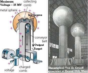
In the search for methods to produce a voltage of larger amplitude and of a more practical nature, machines were developed in which charges were transferred from one terminal to another by means of rotating glass discs or moving belts.
The most notable of these machines is the Van de Graaff generator. It is used today to produce potentials in the order of millions of volts for nuclear research. As these machines have little value outside the field of research, their theory of operation will not be described here.
Voltage Produced by Pressure
One specialized method of generating an emf utilizes the characteristics of certain ionic crystals such as quartz, Rochelle salts, and tourmaline. These crystals have the remarkable ability to generate a voltage whenever stresses are applied to their surfaces.
Thus, if a crystal of quartz is squeezed, charges of opposite polarity will appear on two opposite surfaces of the crystal.
- If the force is reversed and the crystal is stretched, charges will again appear but will be of the opposite polarity from those produced by squeezing.
- If a crystal of this type is given a vibratory motion, it will produce a voltage of reversing polarity between two of its sides.
Quartz or similar crystals can thus be used to convert mechanical energy into electrical energy. This phenomenon called the Piezoelectric Effect, is shown in the figure below.

(A) Non-crystallized structure; (B) crystallized structure; (C) compression of a crystal; (D) decompression of a crystal.
Some common devices that use piezoelectric crystals are microphones, phonograph cartridges, and oscillators used in radio transmitters, receivers, and sonar equipment.
This method of generating an emf is not suitable for applications having large voltage or power requirements but is widely used in sound and communications systems where small signal voltages can be effectively used.
Crystals of this type also possess another interesting property, the “converse piezoelectric effect.” That is, they have the ability to convert electrical energy into mechanical energy.
A voltage impressed across the proper surfaces of the crystal will cause it to expand or contract its surfaces in response to the voltage applied.
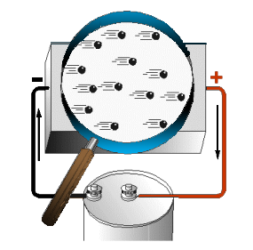
Voltage Produced by Heat
When a length of metal, such as copper, is heated at one end, electrons tend to move away from the hot end toward the cooler end. This is true of most metals.
However, the opposite takes place in some metals, such as iron, and electrons tend to move toward the hot end. These characteristics are illustrated below.
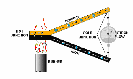
The negative charges (electrons) are moving through the copper away from the heat and through the iron toward the heat. They cross from the iron to the copper through the current meter to the iron at the cold junction. This device is generally referred to as a Thermocouple.
Thermocouples have somewhat greater power capacities than crystals, but their capacity is still very small if compared to some other sources. The thermoelectric voltage in a thermocouple depends mainly on the difference in temperature between the hot and cold junctions.
Consequently, they are widely used to measure temperature and as heat-sensing devices in automatic temperature control equipment. Thermocouples generally can be subjected to much greater temperatures than ordinary thermometers, such as the mercury or alcohol types.
Voltage Produced by Light
When light strikes the surface of a substance, it may dislodge electrons from their orbits around the surface atoms of the substance. This occurs because light has energy, the same as any moving force.
Some substances, mostly metallic ones, are far more sensitive to light than others. More electrons will be dislodged and emitted from the surface of a highly sensitive metal with a given amount of light than will be emitted from a less sensitive substance. The photosensitive (light-sensitive) metal becomes positively charged upon losing electrons, creating an electric force.
The voltage produced in this manner is referred to as a Photoelectric Voltage. The photosensitive materials most commonly used to produce a photoelectric voltage are various silver oxide or copper oxide compounds.
A complete device that operates on the photoelectric principle is referred to as a “photoelectric cell.”
There are many different sizes and types of photoelectric cells in use, and each serves the special purpose for which it is designed. Nearly all, however, have some of the basic features of the photoelectric cells shown below.
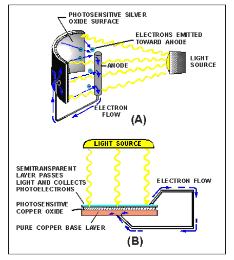
The cell in view A has a curved light-sensitive surface focused on the central anode.
When light from the direction shown strikes the sensitive surface, it emits electrons toward the anode. The more intense the light, the greater the number of electrons emitted. When a wire is connected between the filament and the back, or the dark side of the cell, the accumulated electrons will flow to the dark side.
These electrons will eventually pass through the metal of the reflector and replace the electrons, leaving the light-sensitive surface. Thus, light energy is converted to a flow of electrons, and a usable current is developed.
The cell in view B is constructed in layers.
A base plate of pure copper is coated with light-sensitive copper oxide. An extremely thin semitransparent layer of metal is placed over the copper oxide.
This additional layer serves two purposes:
- It permits the penetration of light to the copper oxide.
- It collects the electrons emitted by the copper oxide.
An externally connected wire completes the electron path, the same as in the reflector-type cell. The photocell’s voltage is used as needed by connecting the external wires to some other device, which amplifies (enlarges) it to a usable level.
The power capacity of a photocell is very small. However, it reacts to light-intensity variations in an extremely short time. This characteristic makes the photocell very useful in detecting or accurately controlling a great number of operations.
For instance, the photoelectric cell, or some form of the photoelectric principle, is used in television cameras, automatic manufacturing process controls, door openers, burglar alarms, and so forth.
Voltage Produced by Chemical Action
Voltage may be produced chemically when certain substances are exposed to chemical action.
If two dissimilar substances (usually metals or metallic materials) are immersed in a solution that produces a greater chemical action on one substance than on the other, a difference of potential will exist between the two. If a conductor is then connected between them, electrons will flow through the conductor to equalize the charge.
This arrangement is called a primary cell. The two metallic pieces are called electrodes, and the solution is called the electrolyte.
The voltaic cell illustrated below is a simple example of a primary cell.

The difference in potential results from the fact that material from one or both of the electrodes goes into solution in the electrolyte, and in the process, ions form in the vicinity of the electrodes.
Due to the electric field associated with the charged ions, the electrodes acquire charges. The potential difference between the electrodes depends principally on the metals used.
The type of electrolyte and the size of the cell have little or no effect on the potential difference produced.
There are two types of primary cells: the wet cell and the dry cell.
In a wet cell, the electrolyte is a liquid. A cell with a liquid electrolyte must remain in an upright position and is not readily transportable. An automotive battery is an example of this type of cell.
The dry cell, much more commonly used than the wet cell, is not actually dry but contains an electrolyte mixed with other materials to form a paste. Flashlights and portable radios are commonly powered by dry cells.
Batteries are formed when several cells are connected together to increase electrical output.
Voltage Produced by Magnetism
 Magnets or magnetic devices are used for thousands of different jobs.
One of the most useful and widely employed applications of magnets is in the production of vast quantities of electric power from mechanical sources.
The mechanical power may be provided by a number of different sources, such as gasoline or diesel engines and water or steam turbines.
However, the final conversion of these source energies to electricity is done by generators employing the principle of electromagnetic induction.
These generators, of many types and sizes, are discussed in other modules in this series.
The important subject to be discussed here is the fundamental operating principle of ALL such electromagnetic-induction generators.
There are three fundamental conditions that must exist before a voltage can be produced by magnetism.
- There must be a conductor in which the voltage will be produced.
- There must be a magnetic field in the conductor’s vicinity.
- There must be relative motion between the field and the conductor.
The conductor must be moved so as to cut across the magnetic lines of force or the field must be moved so that the lines of force are cut by the conductor.
In accordance with these conditions, when a conductor or conductors move across a magnetic field so as to cut the lines of force, electrons within the conductor are propelled in one direction or another. Thus, an electric force, or voltage, is created.
In the figure below, note the presence of the three conditions needed for creating an induced voltage.
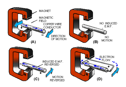
- A magnetic field exists between the poles of the C-shaped magnet.
- There is a conductor (copper wire).
- There is relative motion. The wire is moved back and forth ACROSS the magnetic field.
In view A, the conductor is moving TOWARD the front of the page, and the electrons move from left to right.
The movement of the electrons occurs because of the magnetically induced emf acting on the electrons in the copper. The right-hand end becomes negative, and the left-hand end becomes positive.
The conductor is stopped in view B, motion is eliminated (one of the three required conditions), and there is no longer an induced emf. Consequently, there is no longer any difference in potential between the two ends of the wire.
The conductor in view C is moving away from the front of the page. An induced emf is again created.
However, note carefully that the Reversal of Motion has caused a Reversal of Direction in the induced emf. If a path for electron flow is provided between the ends of the conductor, electrons will leave the negative end and flow to the positive end.
This condition is shown in part in view D. Electron flow will continue as long as the emf exists.
In studying the figure above, it should be noted that the induced emf could also have been created by holding the conductor stationary and moving the magnetic field back and forth.
Electric Current
It has been proven that electrons (negative charges) move through a conductor in response to an electric field. Electron Current Flow will be used throughout this explanation.

Electron current is defined as the directed flow of electrons. The direction of electron movement is from a region of negative potential to a region of positive potential.
Therefore, electric current can be said to flow from negative to positive.
The direction of current flow in a material is determined by the polarity of the applied voltage.
NOTE: In some electrical/electronic communities, the direction of current flow is recognized as being from positive to negative.
Random Drift
All materials are composed of atoms, each of which is capable of being ionized. If some form of energy, such as heat, is applied to a material, some electrons acquire sufficient energy to move to a higher energy level. As a result, some electrons are freed from their parent atoms, becoming ions.
Other forms of energy, particularly light or an electric field, will cause ionization to occur. The number of free electrons resulting from ionization depends upon the quantity of energy applied to a material, as well as the material’s atomic structure.
At room temperature, some materials, classified as conductors, have an abundance of free electrons. Under a similar condition, materials classified as insulators have relatively few free electrons.
In a study of electric current, conductors are of major concern. Conductors are made up of atoms that contain loosely bound electrons in their outer orbits. Due to the effects of increased energy, these outermost electrons frequently break away from their atoms and freely drift throughout the material.
The free electrons, also called mobile electrons, take a path that is not predictable and drift about the material in a haphazard manner. Consequently, such a movement is termed Random Drift.
It is important to emphasize that the random drift of electrons occurs in all materials. The degree of random drift is greater in a conductor than in an insulator.
Directed Drift
Associated with every charged body, there is an electrostatic field. Bodies that are charged alike repel one another, and bodies with unlike charges attract each other. An electron will be affected by an electrostatic field in exactly the same manner as any negatively charged body. It is repelled by a negative charge and attracted by a positive charge. If a conductor has a difference in potential impressed across it, as shown in the figure to the left, a direction is imparted to the random drift.
- This causes the mobile electrons to be repelled away from the negative terminal and attracted toward the positive terminal.
- This constitutes a general migration of electrons from one end of the conductor to the other.
- The directed migration of mobile electrons due to the potential difference is called DIRECTED DRIFT.
- The directed movement of the electrons occurs at a relatively low VELOCITY (rate of motion in a particular direction).
However, the effect of this directed movement is felt almost instantaneously, as shown to the right.
 As a difference in potential is impressed across the conductor, the positive terminal of the battery attracts electrons from point A. Point A now has a deficiency of electrons. As a result, electrons are attracted from point B to point A.
Point B has now developed an electron deficiency. Therefore, it will attract electrons. This same effect occurs throughout the conductor, repeating itself from points D to C.
At the same instant, the positive battery terminal attracted electrons from point A, and the negative terminal repelled electrons toward point D. These electrons are attracted to point D as it gives up electrons to point C. This process is continuous for as long as a difference of potential exists across the conductor.
Though an individual electron moves quite slowly through the conductor, the effect of a directed drift occurs almost instantaneously. As an electron moves into the conductor at point D, an electron is leaving at point A. This action takes place at approximately the speed of light (186,000 miles Per Second).
The Magnitude of Current Flow
Electric current has been defined as the directed movement of electrons. Directed drift is current, and the terms can be used interchangeably.
The expression Directed Drift is particularly helpful in differentiating between electrons’ random and directed motion. However, Current Flow is the terminology most commonly used in indicating a directed movement of electrons.
The magnitude of current flow is directly related to the amount of energy that passes through a conductor as a result of the drift action. An increase in the number of energy carriers (the mobile electrons) or an increase in the energy of the existing mobile electrons would provide an increase in current flow. When an electric potential is impressed across a conductor, there is an increase in the velocity of the mobile electrons, causing an increase in the energy of the carriers.
There is also the generation of an increased number of electrons, providing added carriers of energy. The additional number of free electrons is relatively small; hence, the current flow magnitude primarily depends on the velocity of the existing mobile electrons.
The magnitude of current flow is affected by the difference of potential in the following manner. Initially, mobile electrons are given additional energy because of the repelling and attracting electrostatic field.
- If the potential difference is increased, the electric field will be stronger, the amount of energy imparted to a mobile electron will be greater, and the current will be increased.
- If the potential difference is decreased, the strength of the field is reduced, the energy supplied to the electron is diminished, and the current is decreased.
Measurement of Current
The magnitude of the current is measured in amperes. A current of one ampere is said to flow when one coulomb of charge passes a point in one second.
Remember, one coulomb is equal to the charge of 6.28 x 10¹⁸ electrons.
Frequently, the ampere is much too large a unit for measuring current. Therefore, the milliampere (mA), one-thousandth of an ampere, or the microampere (uA), one-millionth of an ampere, is used.
The device used to measure current is called an Ammeter.
Type of Material
Depending upon their atomic structure, different materials will have different quantities of free electrons. Therefore, the various conductors used in electrical applications have different values of resistance.
Consider a simple metallic substance. Most metals are crystalline in structure and consist of atoms that are tightly bound in the lattice network.
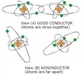 The atoms of such elements are so close together that the electrons in the atom’s outer shell are associated with one atom as much as with its neighbor. As illustrated in view A.
As a result, the force of attachment of an outer electron with an individual atom is practically zero.
Depending on the metal, at least one electron, sometimes two, and in a few cases, three electrons per atom exist in this state. In such a case, a relatively small amount of additional electron energy would free the outer electrons from the attraction of the nucleus.
At normal room temperature, materials of this type have many free electrons and are good conductors. Good conductors will have low resistance.
If the atoms of a material are farther apart, as illustrated in view B, the electrons in the outer shells will not be equally attached to several atoms as they orbit the nucleus.
- They will be attracted by the nucleus of the parent atom only.
- Therefore, a greater amount of energy is required to free any of these electrons.
- Materials of this type are poor conductors and, therefore, have high resistance.
Copper, silver, gold, and aluminum are good conductors. Therefore, materials composed of their atoms would have low resistance.
- The element copper is the conductor most widely used throughout electrical applications.
- Silver has a lower resistance than copper, but its cost limits usage to circuits where a high conductivity is demanded.
- Aluminum, which is considerably lighter than copper, is used as a conductor when weight is a major factor.
Effect Of Cross-Sectional Area
Cross-sectional area greatly affects the magnitude of resistance. If the cross-sectional area of a conductor is increased, a greater quantity of electrons is available for movement through the conductor.
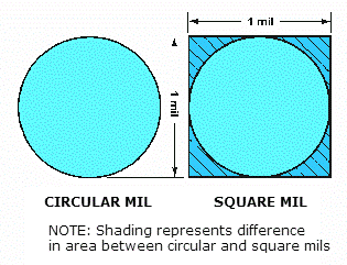 Therefore, a larger current will flow for a given amount of applied voltage. An increase in current indicates that when the cross-sectional area of a conductor is increased, the resistance must have decreased.
If the cross-sectional area of a conductor is decreased, the number of available electrons decreases, and for a given applied voltage, the current through the conductor decreases. A decrease in current flow indicates that when the cross-sectional area of a conductor is decreased, the resistance must have increased.
Thus, the resistance of a conductor is inversely proportional to its cross-sectional area.
The diameter of conductors used in electronics is often only a fraction of an inch. Therefore, the diameter is expressed in mils (thousandths of an inch). It is also standard practice to assign the unit circular mil to the cross-sectional area of the conductor.
The circular mil is found by squaring the diameter when the diameter is expressed in mils. Thus, if the diameter is 35 mils (0.035 inch), the circular mil area is equal to (35) 2 or 1225 circular mils. A comparison between a square mil & a circular mil is illustrated in the image to the right.
Effect Of Conductor Length
The length of a conductor is also a factor that determines the resistance of a conductor. If the length of a conductor is increased, the amount of energy given up increases. As free electrons move from atom to atom, some energy is given off as heat. The longer a conductor is, the more energy is lost to heat.
The additional energy loss subtracts from the energy being transferred through the conductor, resulting in a decrease in current flow for a given applied voltage. A decrease in current flow indicates an increase in resistance since the voltage was held constant. Therefore, if the length of a conductor is increased, the resistance increases.
The resistance of a conductor is directly proportional to its length.
Effect Of Temperature
Temperature changes affect the resistance of materials in different ways. In some materials, an increase in temperature causes an increase in resistance, whereas, in others, an increase in temperature causes a decrease in resistance.
The amount of change of resistance per unit change in temperature is known as the Temperature Coefficient.
- If a material’s resistance increases with an increase in temperature, it is said to have a Positive Temperature Coefficient.
- A material whose resistance decreases with an increase in temperature has a Negative Temperature Coefficient.
Most conductors used in electronic applications have a positive temperature coefficient. However, carbon, a frequently used material, is a substance having a negative temperature coefficient.
Several materials, such as the alloys constantan and manganin, are considered to have a Zero Temperature Coefficient because their resistance remains relatively constant for changes in temperature.
Conductance
Electricity is a study that is frequently explained in terms of opposites. The term that is the opposite of resistance is Conductance. Conductance is the ability of a material to pass electrons.
The factors that affect the magnitude of resistance are exactly the same for conductance, but they affect conductance in the opposite manner. Therefore, conductance is directly proportional to the area and inversely proportional to the length of the material.
The temperature of the material is definitely a factor, but assuming a constant temperature, the conductance of a material can be calculated. The unit of conductance is the MHO (G), which is ohm spelled backward.
Recently, the term mho has been re-designated SIEMENS(S). Whereas the symbol used to represent resistance (R) is the Greek letter omega (Ω), the symbol used to represent conductance (G) is (S).
The relationship between resistance (R) and conductance (G) or (S) is a reciprocal one. (A reciprocal of a number is one divided by that number).
In terms of resistance and conductance:
 Electrical Resistors
Resistance is a property of every electrical component. At times, its effects will be undesirable. However, resistance is used in many varied ways.
Resistors are components manufactured to possess specific values of resistance. They are manufactured in many types and sizes.
A resistor is shown as a series of jagged lines when drawn using its schematic representation, as illustrated in the table below.
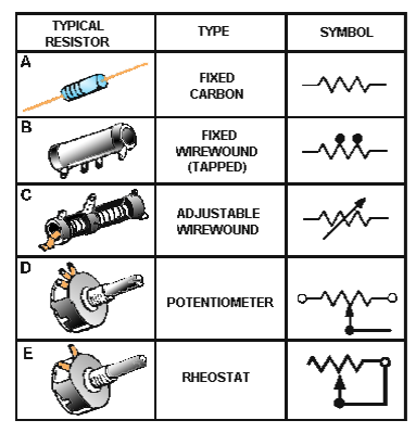 Composition of Resistors: One of the most common types of resistors is the molded composition, usually referred to as the carbon resistor.
These resistors are manufactured in a variety of sizes and shapes. The chemical composition of the resistor determines its ohmic value and is accurately controlled by the manufacturer in the development process. They are made in ohmic values that range from one ohm to millions of ohms.
The physical size of the resistor is related to its wattage rating, which is the ability of a resistor to dissipate the heat caused by the resistance.
Carbon resistors, as you might suspect, have as their principal ingredient the element carbon. In the manufacturer of carbon resistors, fillers or binders are added to the carbon to obtain various resistor values. Examples of these fillers are clay, bakelite, rubber, and talc. These fillers are doping agents and cause the overall conduction characteristics to change.
Carbon resistors are the most common resistors found because they are easy to manufacture, inexpensive, and have an adequate tolerance for most electrical and electronic applications.
Their prime disadvantage is that they have a tendency to change value as they age. One other disadvantage of carbon resistors is their limited power handling capacity. The disadvantage of carbon resistors can be overcome by the use of wirewound resistors.
Wirewound resistors have very accurate values and possess a higher current handling capability than carbon resistors.
German Silver, which is composed of copper, nickel, and zinc, is frequently used to manufacture wire-wound resistors. The qualities and quantities of these elements present in the wire determine the resistivity of the wire. (The resistivity of the wire is the measure or ability of the wire to resist current. Usually, the percent of nickel in the wire determines the resistivity.)
One disadvantage of the wirewound resistor is that it takes a large amount of wire to manufacture a resistor of high ohmic value, thereby increasing the cost. A variation of the wirewound resistor provides an exposed surface to the resistance wire on one side. An adjustable tap is attached to this side.
Such resistors, sometimes with two or more adjustable taps, are used as voltage dividers in power supplies and other applications where a specific voltage is desired to be “tapped” off.
There are two kinds of resistors: Fixed and Variable.
The fixed resistor will have one value and will never change (other than through temperature, age, etc.). The resistors shown in A and B are classed as fixed resistors.
- The tapped resistor illustrated in B has several fixed taps and makes more than one resistance value available.
- The sliding contact resistor shown in C has an adjustable collar that can be moved to tap off any resistance within the ohmic value range of the resistor.
There are two types of variable resistors; one is called a Potentiometer, and the other a Rheostat (see views D and E of the table above).
The Potentiometer has a wide range of values but usually has a limited current-handling capability. Potentiometers are always connected as voltage dividers.
An example of the potentiometer is the volume control on your radio, and an example of the rheostat is the dimmer control for the dash lights in an automobile; however, there is a slight difference between them.
Rheostats usually have two connections, one fixed and the other moveable. Any variable resistor can properly be called a rheostat. The potentiometer always has three connections, two fixed and one moveable. Generally, the rheostat has a limited range of values and a high current-handling capability.
Wattage Rating
When a current is passed through a resistor, heat is developed within the resistor. The resistor must be capable of dissipating this heat into the surrounding air; otherwise, the temperature of the resistor rises, causing a change in resistance or possibly causing the resistor to burn out.
The ability of the resistor to dissipate heat depends upon the design of the resistor itself. This ability to dissipate heat depends on the amount of surface area which is exposed to the air.
Therefore, a resistor designed to dissipate a large amount of heat must have a large physical size. The heat-dissipating capability of a resistor is measured in WATTS (this unit will be explained later in a future module).
Some of the more common wattage ratings of carbon resistors are one-eighth watt, one-fourth watt, one-half watt, one watt, and two watts. In some of the newer state-of-the-art circuits of today, much smaller wattage resistors are used.
Generally, the type that you will be able to physically work with is of the values given. The higher the wattage rating of the resistor, the larger the physical size. Resistors that dissipate very large amounts of power (watts) are usually wirewound resistors. Wirewound resistors with wattage ratings up to 50 watts are not uncommon.
The image below shows some resistors which have different wattage ratings. Notice the relative sizes of the resistors.
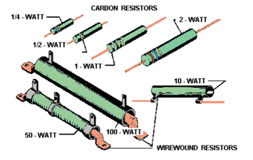
Standard Color Code System For Resisters
Four bands are painted on the resistor in the standard color code system, as shown below.
- The color of the first band indicates the value of the first significant digit.
- The color of the second band indicates the value of the second significant digit.
- The third color band represents a decimal multiplier by which the first two digits must be multiplied to obtain the resistance value of the resistor.
- The fourth band on the resistor indicates the tolerance; that is, the manufacturer’s allowable ohmic deviation above and below the numerical value indicated by the resistor’s color code.
The colors for the bands are shown above, and their corresponding values are shown below.
 Using the example colors shown above.
- Since red is the color of the first band, the first significant digit is 2.
- The second band is violet. Therefore, the second significant digit is 7.
- The third band is orange, indicating that the number formed from reading the first two bands is multiplied by 1000.
In this case, 27 x 1000 = 27,000 ohms.
The fourth band is the color silver, which indicates a tolerance of 10 percent. In other words, the resistor’s actual value may fall within 10 percent above or 10 percent below the value indicated by the color code.
This resistor has an indicated value of 27,000 ohms. Its tolerance is 10 percent x 27,000 ohms or 2,700 ohms. Therefore, the resistor’s actual value is somewhere between 24,300 ohms and 29,700 ohms.
When measuring resistors, you will find situations in which the quantities to be measured may be extremely large, and the resulting number using the basic unit, the ohm, may prove too cumbersome. Therefore, a metric system prefix is usually attached to the basic unit of measurement to provide a more manageable unit.
Two of the most commonly used prefixes are kilo and mega.
- Kilo is the prefix used to represent thousand and is abbreviated k.
- Mega is the prefix used to represent a million and is abbreviated M.
In the example given above, the 27,000-ohm resistor could have been written as 27 kilohms or 27 kΩ
Other examples are: 1000 ohms = 1 kW: 10000 ohms = 10 kΩ: 100000 ohms = 100 kΩ
Likewise, 1,000,000 ohms is written as one megohm or one MΩ and 10,000,000 ohms = 10 MΩ
Simplifying The Color Code
Resistors are the most common components used in electronics. The technician must identify, select, check, remove, and replace resistors.
Resistors and resistor circuits are usually the easiest branches of electronics to understand. The resistor color code sometimes presents problems to a technician. It really should not because once the resistor color code is learned, you should remember it for the rest of your life.
Black, brown, red, orange, yellow, green, blue, violet, gray, white – this is the order of colors you should know automatically.
There is a memory aid that will help you remember the code in its proper order.
Each word starts with the first letter of the colors.
If you match it up with the color code, you will not forget the code.
Buy Beer Regularly Or Your Good Buddies Visits Gradually Wain
or:
- Black — Buy
- Brown — Beer
- Red — Regularly
- Orange — Or
- Yellow — Your
- Green — Good
- Blue — Buddies
- Violet — Visits
- Gray — Gradually
- White — Wain
There are many other memory aid sentences that you might want to ask about from experienced technicians. You might find one of the other sentences easier to remember.
There is still a good chance that you will make a mistake on a resistor’s color band. Most technicians do this at one time or another. If you make a mistake on the first two significant colors, it usually is not too serious. If you make a miscue on the third band, you are in trouble because the value is going to be at least ten times too high or too low.
Some important points to remember about the third band are:
When the third band is:
- Black, the resistor’s value is less than 100 ohms.
- Brown, the resistor’s value is in hundreds of ohms.
- Red, the resistor’s value is in thousands of ohms.
- Orange, the resistor’s value is in tens of thousands of ohms.
- Yellow, the resistor’s value is in hundreds of thousands of ohms.
- Green, the resistor’s value is in megohms.
- Blue, the resistor’s value is in tens of megohms or more.
Although you may find any of the above colors in the third band, red, orange, and yellow are the most common. In some cases, the third band will be silver or gold. You multiply the first two bands by 0.1 if it is gold and 0.01 if it is silver.
The fourth band, which is the tolerance band, usually does not present too much of a problem. If there is no fourth band, the resistor has a 20-percent tolerance; a fourth gold band indicates a 5-percent tolerance, and a a fourth silver band indicates a 10-percent tolerance.
The fifth band indicates the reliability level per 1,000 hours of operation as follows:
- Brown 1.0%
- Red 0.1%
- Orange 0.01%
- Yellow 0.001%
Some resistors, both wirewound and composition, will not use the resistor color code. These resistors will have the ohmic value and tolerance imprinted on the resistor itself.