
Lesson 1 of Article 250 Grounding and Bonding, reviews Article 100 and 250 Part 1 General
Article 250 is the largest article in the National Electrical Code. It is organized into 10 different parts, each dealing with specific requirements regarding grounding and bonding requirements.
These specific parts are as follows:
(I) General
(II) System Grounding
(III) Grounding Electrode System and Grounding Electrode Conductor
(IV) Enclosure, Raceway, and Service Cable Connections
(V) Bonding
(VI) Equipment Grounding and Equipment Grounding Conductors
(VII) Methods of Equipment Grounding Conductor Connections
(VIII) Direct-Current Systems
(IX) Instruments, Meters, and Relays
(X) Grounding of Systems and Circuits of over 1000 Volts
The scope of this article covers general requirements for grounding and bonding of electrical installations.
BONDING is the permanent joining of metallic pieces to form a conducting path which ensures safe electrical continuity. Bonding is done to protect people and equipment against electrical shock and provides safety in the event of a fault current. If you come into contact with a metal electrical device during a fault condition while touching a metal object connected to the earth, you will most likely receive an electrical shock. However, if all metal objects are connected (bonded) together, you are safe because they are at the same potential, completely removing the possibility of an electrical shock.
GROUNDING is any accidental or intentional connection between an electrical circuit or equipment and the earth. Grounding ensures all metal parts of an electrical circuit are connected to the earth, thus ensuring zero voltage. More than two conductive objects are required to create a Bonding connection, usually done with the help of a conductor. These conductors are usually wires or rods. Grounding has no impact on the regular function of an electrical system.
BONDING and GROUNDING in residential, commercial, industrial, and institutional buildings are critical. An electrical system should be provided with a return path, starting from the termination to the source of power to properly work. People often end up confusing GROUNDING and BONDING.
Article 100 – 2023 NEC
Before we begin reviewing Article 250, let’s review the following definitions located in Article 100 relating to Grounding and Bonding
Article 100 Definitions.
Scope. This article contains only those definitions essential to the application of this Code. It is not intended to include commonly defined general terms or commonly defined technical terms from related codes and standards. An article number in parentheses following the definition indicates that the definition only applies to that article.
Informational Note: A definition that is followed by a reference in brackets has been extracted from one of the following standards. Only editorial changes were made to the extracted text to make it consistent with this Code.
NFPA 30A-2021, Code for Motor Fuel Dispensing Facilities and Repair Garages
NFPA 33-2021, Standard for Spray Application Using Flammable or Combustible Materials
NFPA 75-2020, Standard for the Fire Protection of Information Technology Equipment
NFPA 79-2021, Electrical Standard for Industrial Machinery
NFPA 99-2021, Health Care Facilities Code
NFPA 101®-2022, Life Safety Code®
NFPA 110-2019, Standard for Emergency and Standby Power Systems
NFPA 303-2021, Fire Protection Standard for Marinas and Boatyards
NFPA 307-2021, Standard for the Construction and Fire Protection of Marine Terminals, Piers, and Wharves
NFPA 499-2021, Recommended Practice for the Classification of Combustible Dusts and of Hazardous (Classified) Locations for Electrical Installations in Chemical Process Areas
NFPA 501-2022, Standard on Manufactured Housing
NFPA 790-2021, Standard for Competency of Third-Party Field Evaluation Bodies
NFPA 1192-2021, Standard on Recreational Vehicles
Bonded (Bonding).
Connected to establish electrical continuity and conductivity. (CMP-5)
Electrical bonding is the practice of intentionally electrically connecting all exposed metal items not designed to carry electricity in a room or building as protection from electric shock. If a failure of electrical insulation occurs, all bonded metal objects in the room will have substantially the same electrical potential, so that an occupant of the room cannot touch two objects with significantly different potentials. Even if the connection to distant earth ground is lost, the occupant will be protected from dangerous potential differences.
Bonding Conductor (Bonding Jumper).
A conductor that ensures the required electrical conductivity between metal parts that are required to be electrically connected. (CMP-5)
Bonding Jumper, Equipment. (Equipment Bonding Jumper)
The connection between two or more portions of the equipment grounding conductor. (CMP-5)
Bonding Jumper, Main. (Main Bonding Jumper)
The connection between the grounded circuit conductor and the equipment grounding conductor, or the supply-side bonding jumper, or both, at the service. (CMP-5)
Bonding Jumper, Supply-Side. (Supply-Side Bonding Jumper)
A conductor installed on the supply side of a service or within a service equipment enclosure(s) or for a separately derived system that ensures the required electrical conductivity between metal parts required to be electrically connected. (CMP-5)
Bonding Jumper, System. (System Bonding Jumper)
The connection between the grounded circuit conductor and the supply-side bonding jumper, or the equipment grounding conductor, or both, at a separately derived system. (CMP-5)
Ground.
The earth. (CMP-5)
Ground Fault.
An unintentional, electrically conductive connection between an ungrounded conductor of an electrical circuit and the normally non-current-carrying conductors, metal enclosures, metal raceways, metal equipment, or earth. (CMP-5)
Ground-Fault Circuit Interrupter (GFCI).
A device intended for the protection of personnel that functions to de-energize a circuit or portion thereof within an established period of time when a ground-fault current exceeds the values established for a Class A device. (CMP-2)
Informational Note: See UL 943, Standard for Ground-Fault Circuit Interrupters, for further information. Class A ground-fault circuit interrupters trip when the ground-fault current is 6 mA or higher and do not trip when the ground-fault current is less than 4 mA
 Ground-Fault Circuit Interrupter, Special Purpose (SPGFCI). (Special Purpose Ground-Fault Circuit Interrupter)
A device intended for the detection of ground-fault currents, used in circuits with voltage to ground greater than 150 volts, that functions to de-energize a circuit or portion of a circuit within an established period of time when a ground-fault current exceeds the values established for Class C, D, or E devices. (CMP-2)
Informational Note: See UL 943C, Outline of Investigation for Special Purpose Ground-Fault Circuit Interrupters, for information on Classes C, D, or E special purpose ground-fault circuit interrupters.
Ground-Fault Current Path.
An electrically conductive path from the point of a ground fault on a wiring system through normally non–current-carrying conductors, grounded conductors, equipment, or the earth to the electrical supply source. (CMP-5)
Informational Note: Examples of ground-fault current paths are any combination of equipment grounding conductors, metallic raceways, metallic cable sheaths, electrical equipment, and any other electrically conductive material such as metal, water, and gas piping; steel framing members; stucco mesh; metal ducting; reinforcing steel; shields of communications cables; grounded conductors; and the earth itself.
Ground-Fault Current Path, Effective. (Effective Ground-Fault Current Path)
An intentionally constructed, low-impedance electrically conductive path designed and intended to carry current during ground-fault events from the point of a ground fault on a wiring system to the electrical supply source and that facilitates the operation of the overcurrent protective device or ground-fault detectors. (CMP-5)
Ground-Fault Detector-Interrupter, dc (GFDI).
A device that provides protection for PV system dc circuits by detecting a ground fault and could interrupt the fault path in the dc circuit. (690) (CMP-4)
Informational Note: See UL 1741, Standard for Inverters, Converters, Controllers and Interconnection System Equipment for Use with Distributed Energy Resources, and UL 62109, Standard for Power Converters for use in Photovoltaic Power Systems, for further information on GFDI equipment.
Ground-Fault Protection of Equipment(GFPE).
A system intended to provide protection of equipment from damaging line-to-ground fault currents by operating to cause a disconnecting means to open all ungrounded conductors of the faulted circuit. This protection is provided at current levels less than those required to protect conductors from damage through the operation of a supply circuit overcurrent device. (CMP-5)
Grounded, Functionally. (Functionally Grounded)
A system that has an electrical ground reference for operational purposes that is not solidly grounded. (CMP-4)
Informational Note: A functionally grounded system is often connected to ground through an electronic means internal to an inverter or charge controller that provides ground-fault protection. Examples of operational purposes for functionally grounded systems include ground-fault detection and performance-related issues for some power sources.
Grounded, Solidly. (Solidly Grounded)
Connected to ground without inserting any resistor or impedance device. (CMP-5)
Grounded Conductor.
A system or circuit conductor that is intentionally grounded. (CMP-5)
Informational Note: Although an equipment grounding conductor is grounded, it is not considered a grounded conductor.
Grounded System, Impedance. (Impedance Grounded System)
An electrical system that is grounded by intentionally connecting the system neutral point to ground through an impedance device. (CMP-5)
Grounding Conductor, Equipment (EGC). (Equipment Grounding Conductor)
A conductive path(s) that is part of an effective ground-fault current path and connects normally non-current-carrying metal parts of equipment together and to the system grounded conductor or to the grounding electrode conductor, or both. (CMP-5)
Informational Note No. 1: It is recognized that the equipment grounding conductor also performs bonding.
Informational Note No. 2: See 250.118 for a list of acceptable equipment grounding conductors.
Grounding Conductor, Impedance. (Impedance Grounding Conductor)
A conductor that connects the system neutral point to the impedance device in an impedance-grounded system. (CMP-5)
Grounding Electrode.
A conducting object through which a direct connection to Earth is established. (CMP-5)
Grounding Electrode Conductor (GEC).
A conductor used to connect the system grounded conductor or the equipment to a grounding electrode or to a point on the grounding electrode system. (CMP-5)
Intersystem Bonding Termination (IBT).
A device that provides a means for connecting intersystem bonding conductors for communications systems to the grounding electrode system. (CMP-16)
TO RECEIVE DIGITAL ACCESS TO NFPA CODES & STANDARDS WITH ENHANCED CONTENT, SUBSCRIBE TO NFPA LINK!
Article 250 Grounding and Bonding
250.1 Scope
250.4 General Requirements for Grounding and Bonding
(A) Grounded Systems.
(B) Ungrounded Systems.
250.6 Objectionable Current
(A) Arrangement to Prevent Objectionable Current.
(B) Alterations to Stop Objectionable Current.
(C) Currents Not Classified as Objectionable Currents.
(D) Limitations to Permissible Alterations.
(E) Isolation of Objectionable Direct-Current from Cathodic Protection Systems.
250.8 Connection of Grounding and Bonding Equipment
(A) Permitted Methods.
(B) Methods Not Permitted.
250.10 Protection of Ground Clamps and Fittings
250.12 Clean Surfaces
Part I. General
250.1 Scope
250.1 Scope.
This article covers general requirements for grounding and bonding of electrical installations and the following specific requirements:
(1) Systems, circuits, and equipment required, permitted, or not permitted to be grounded
(2) Circuit conductor to be grounded on grounded systems
(3) Location of grounding connections
(4) Types and sizes of grounding and bonding conductors and electrodes
(5) Methods of grounding and bonding
(6) Conditions under which isolation, insulation, or guards are permitted to be substituted for grounding
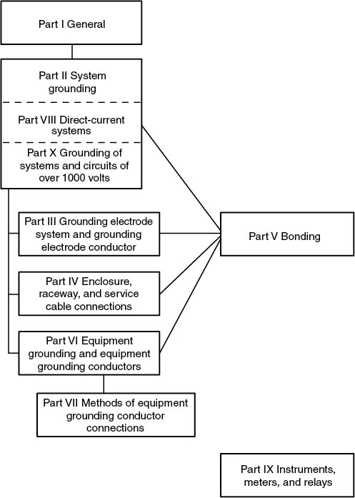
Informational Note: See Informational Note Figure 250.1 for information on the organization of this article covering grounding and bonding requirements.
![]()
Informational Note Figure 250.1 Grounding and Bonding.
Enhanced Code Analysis:
While often used synonymously in practical settings, the terms “grounding” and “bonding” represent distinct concepts with different implications as defined by Article 250. These two concepts, however, are not mutually exclusive and often overlap in application.
For instance, a single physical act like attaching the Equipment Grounding Conductor (EGC) to the grounding terminal of a duplex receptacle simultaneously achieves both a bonding and a grounding connection.
This illustrates how these two essential safety mechanisms can coexist and complement each other in electrical installations.
250.4 General Requirements for Grounding and Bonding
(A) Grounded Systems.
(B) Ungrounded Systems.
250.4 General Requirements for Grounding and Bonding.
The following general requirements identify what grounding and bonding of electrical systems are required to accomplish. The prescriptive methods contained in this article shall be followed to comply with the performance requirements of this section.
![]() (A) Grounded Systems.
(A) Grounded Systems.
(1) Electrical System Grounding.
Electrical systems that are grounded shall be connected to earth in a manner that will limit the voltage imposed by lightning, line surges, or unintentional contact with higher-voltage lines and that will stabilize the voltage to earth during normal operation.
Informational Note No. 1: An important consideration for limiting the imposed voltage is the routing of bonding and grounding electrode conductors so that they are not any longer than necessary to complete the connection without disturbing the permanent parts of the installation and so that unnecessary bends and loops are avoided.
Informational Note No. 2: See NFPA 780-2020, Standard for the Installation of Lightning Protection Systems, for information on installation of grounding and bonding for lightning protection systems.
(2) Grounding of Electrical Equipment.
Normally non–current-carrying conductive materials enclosing electrical conductors or equipment, or forming part of such equipment, shall be connected to earth so as to limit the voltage to ground on these materials.
(3) Bonding of Electrical Equipment.
Normally, non-current-carrying conductive materials enclosing electrical conductors or equipment or forming part of such equipment shall be connected together and to the electrical supply source in a manner that establishes an effective ground-fault current path.
(4) Bonding of Electrically Conductive Materials and Other Equipment.
Normally non-current-carrying electrically conductive materials that are likely to become energized shall be connected together and to the electrical supply source in a manner that establishes an effective ground-fault current path.
(5) Effective Ground-Fault Current Path.
Electrical equipment and wiring and other electrically conductive material likely to become energized shall be installed in a manner that creates a low-impedance circuit facilitating the operation of the overcurrent device or ground detector for impedance grounded systems. It shall be capable of safely carrying the maximum ground-fault current likely to be imposed on it from any point on the wiring system where a ground fault occurs to the electrical supply source. The earth shall not be considered as an effective ground-fault current path.
![]() (B) Ungrounded Systems.
(B) Ungrounded Systems.
(1) Grounding Electrical Equipment.
Non–current-carrying conductive materials enclosing electrical conductors or equipment, or forming part of such equipment, shall be connected to earth in a manner that will limit the voltage imposed by lightning or unintentional contact with higher-voltage lines and limit the voltage to ground on these materials.
Informational Note: See NFPA 780-2020, Standard for the Installation of Lightning Protection Systems, for information on installation of grounding and bonding for lightning protection systems.
(2) Bonding of Electrical Equipment.
Non–current-carrying conductive materials enclosing electrical conductors or equipment, or forming part of such equipment, shall be connected together and to the supply system grounded equipment in a manner that creates a low-impedance path for ground-fault current that is capable of carrying the maximum fault current likely to be imposed on it.
(3) Bonding of Electrically Conductive Materials and Other Equipment.
Electrically conductive materials that are likely to become energized shall be connected together and to the supply system grounded equipment in a manner that creates a low-impedance path for ground-fault current that is capable of carrying the maximum fault current likely to be imposed on it.
(4) Path for Fault Current.
Electrical equipment, wiring, and other electrically conductive material likely to become energized shall be installed in a manner that creates a low-impedance circuit from any point on the wiring system to the electrical supply source to facilitate the operation of overcurrent devices should a second ground fault from a different phase occur on the wiring system. The earth shall not be considered as an effective fault-current path.
Enhanced Code Analysis:
250.4 General Requirements for Grounding and Bonding: The provisions outlined in NEC 250.4(A) and (B) detail the overarching performance objectives for the grounding and bonding of electrical systems and equipment. However, these sections do not offer specific details or prescriptive guidelines regarding aspects such as the exact connection points or the sizing of grounding and bonding conductors. The performance objectives stated in 250.4 serve to give users a clear understanding of the intended outcomes that should be achieved by applying the prescriptive rules found in the rest of Article 250. This approach ensures that while adhering to specific regulations, the fundamental goals of safety and system integrity are consistently met.
250.4(A)(5) Effective Ground-Fault Current Path: The purpose of establishing an effective ground-fault current path is not solely to enable the activation of an Overcurrent Protective Device (OCPD). In certain scenarios, such as with high-impedance grounded systems, the primary performance objective shifts. In these systems, the key goal is to guarantee the functioning of the necessary ground detector. This detector is responsible for triggering an alarm or another form of signal, which serves to alert users to the presence of a ground-fault condition. This approach highlights the adaptability of grounding objectives to different system types, focusing on the most effective method of fault detection and indication based on the system’s specific characteristics.
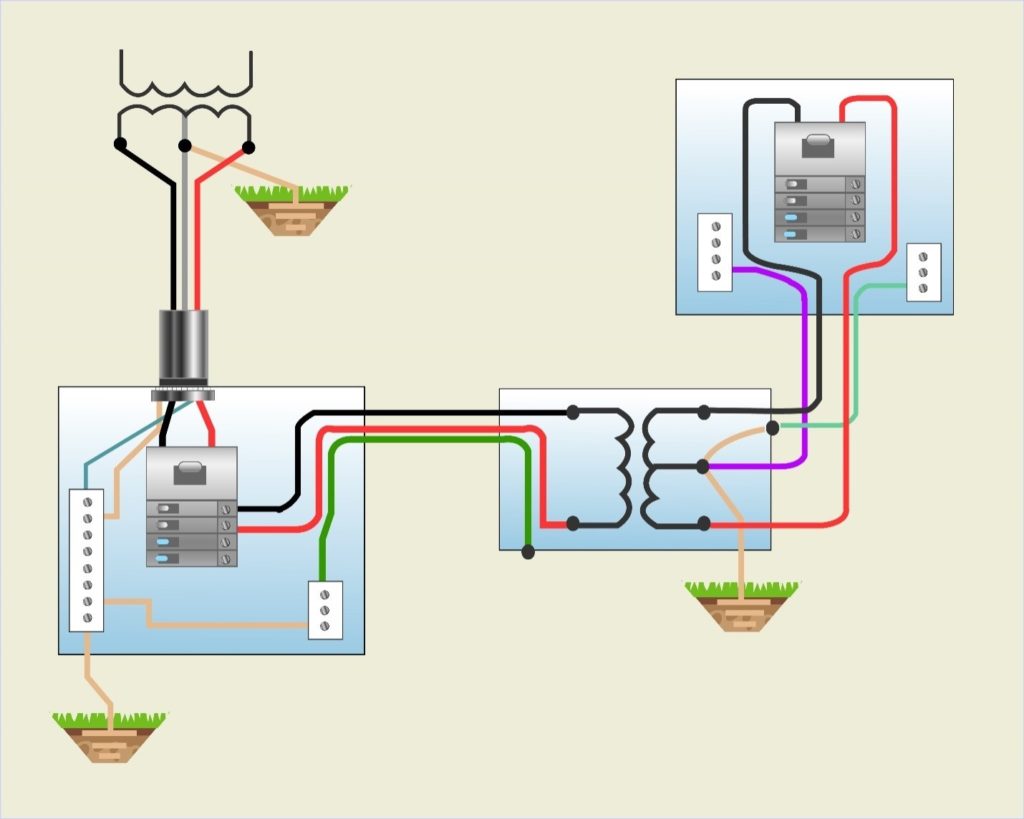
250.4(B)(4) Path for Fault Current: In both grounded and ungrounded electrical systems, the performance requirements for grounding can be broadly divided into two main functions: system grounding and equipment grounding. These two functions are distinct and are typically unified only at the point of supply, such as at the service equipment or in a separately derived system.
Grounding refers to the deliberate connection of a circuit conductor either directly to the earth or to a substitute grounding medium. Generally, this connection is established at the supply source, like a transformer, and at the main service disconnecting means of the premises utilizing the electrical energy. In “ungrounded” systems, while there is no intentionally grounded circuit conductor, equipment still needs to be grounded. This is achieved using an Equipment Grounding Conductor (EGC) that connects to a grounding electrode system.
The grounding serves two primary purposes:
- To limit voltages induced by lightning strikes or accidental contact with higher voltage supply conductors.
- To stabilize the voltage during normal operations, ensuring that the voltage remains at a consistent level relative to the ground. This stability is crucial as it ensures that any equipment connected to the system is exposed only to the expected potential difference.
The provided exhibit illustrates a grounded single-phase, 3-wire service originating from a utility transformer. Within the enclosure of the service disconnecting means, the system’s grounded conductor is intentionally connected to a grounding electrode through the Grounding Electrode Conductor (GEC). This setup exemplifies the standard approach to grounding in such systems.

Crucially, it is the bonding of the Equipment Grounding Conductor (EGC) bus to the neutral bus that enables the activation of Overcurrent Protective Devices (OCPDs) or relays during a ground-fault condition. This function is facilitated by the bonding within the system, rather than by the grounding connection of the system to the earth via the grounding electrode system. This distinction highlights the importance of proper bonding within the electrical system to ensure safety and functionality, especially in fault conditions.
250.6 Objectionable Current
(A) Arrangement to Prevent Objectionable Current.
(B) Alterations to Stop Objectionable Current.
(C) Currents Not Classified as Objectionable Currents.
(D) Limitations to Permissible Alterations.
(E) Isolation of Objectionable Direct-Current from Cathodic Protection Systems.
250.6 Objectionable Current.
(A) Arrangement to Prevent Objectionable Current.
The grounding and bonding of electrical systems, circuit conductors, surge arresters, surge-protective devices, and conductive normally non–current-carrying metal parts of equipment shall be installed and arranged in a manner that will prevent objectionable current.
![]() (B) Alterations to Stop Objectionable Current.
(B) Alterations to Stop Objectionable Current.
If the use of multiple grounding or bonding connections results in objectionable current and the requirements of 250.4(A)(5) or (B)(4) are met, one or more of the following alterations shall be permitted:
(1) Discontinue one or more but not all of such grounding or bonding connections.
(2) Change the locations of the grounding or bonding connections.
(3) Interrupt the continuity of the conductor or conductive path causing the objectionable current.
(4) Take other remedial and approved action.
![]() (C) Currents Not Classified as Objectionable Currents.
(C) Currents Not Classified as Objectionable Currents.
Currents resulting from abnormal conditions such as ground faults, and from currents resulting from required grounding and bonding connections shall not be classified as objectionable current for the purposes specified in 250.6(A) and (B).
(D) Limitations to Permissible Alterations.
This section shall not be considered as permitting electronic equipment to be operated on ac systems or branch circuits that are not connected to an equipment grounding conductor as required by this article. Currents that introduce electromagnetic interference or data errors in electronic equipment shall not be considered the objectionable currents addressed in this section.
(E) Isolation of Objectionable Direct-Current from Cathodic Protection Systems.
If isolation of objectionable direct currents from a cathodic protection system is required, a listed isolator device shall be permitted in the equipment grounding conductor path to provide an effective return path for ac ground-fault current while blocking the flow of direct currents.
Enhanced Code Analysis:
250.6(B) Alterations to Stop Objectionable Current: Electronic equipment can be sensitive to stray currents, which may arise from circulating currents on Equipment Grounding Conductors (EGCs), metal raceways, and building steel. These currents can create potential differences between the ground and the neutral of electronic equipment, potentially affecting their performance. When designing installations, it’s important for designers to find ways to shield electronic equipment from the impacts of such stray circulating currents.
However, isolating electronic equipment from all other power equipment by disconnecting it from the power equipment ground is not an appropriate solution. Similarly, removing the equipment grounding means or incorporating nonmetallic spacers in the metallic raceway system are not advisable practices. These approaches go against the fundamental principles of safety grounding as outlined in Article 250 of the NEC. Additionally, grounding electronic equipment to an earth ground that is isolated from the common power system ground can create a potential difference, posing a shock hazard.
Such isolation is problematic because it fails to establish a low-impedance path for ground-fault current to return to the power source, which is essential for the activation of Overcurrent Protective Devices (OCPD). NEC Section 250.6(B) explicitly prohibits disconnecting all safety grounding and bonding connections to electronic equipment as a means to mitigate electromagnetic interference (EMI) issues.
For further details on the limitations regarding alterations in grounding and bonding, NEC 250.6(D) should be consulted. This section provides guidance on what modifications are permissible.
250.8 Connection of Grounding and Bonding Equipment
(A) Permitted Methods.
(B) Methods Not Permitted.
250.8 Connection of Grounding and Bonding Equipment.
(A) Permitted Methods.
Equipment grounding conductors, grounding electrode conductors, and bonding jumpers shall be connected by one or more of the following means:
(1) Listed pressure connectors
(2) Terminal bars
(3) Pressure connectors listed as grounding and bonding equipment
(4) Exothermic welding process
(5) Machine screw-type fasteners that engage not less than two threads or are secured with a nut
(6) Thread-forming machine screws that engage not less than two threads in the enclosure
(7) Connections that are part of a listed assembly
(8) Other listed means
(B) Methods Not Permitted.
Connection devices or fittings that depend solely on solder shall not be used.
Enhanced Code Analysis:
250.8 Connection of Grounding and Bonding Equipment: This section’s explicit mention of machine screws and thread-forming machine screws as acceptable methods for connecting grounding and bonding conductors or terminals implies that other types of screws, like sheet metal screws or drywall screws, are not permitted for these connections. The reason for this is that coarse-threaded screws do not meet the product certification standard requirements for grounding and bonding connections, which require the screw to engage at least two full threads into a metal box or other metal enclosure.
When it comes to listed pressure connectors, such as twist-on wire connectors, they do not need to be specifically listed for grounding and bonding purposes. Therefore, the use of listed pressure connectors, even those not colored green, is acceptable for connecting grounding and bonding conductors.
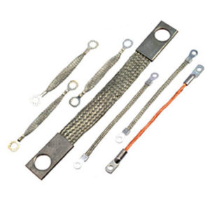
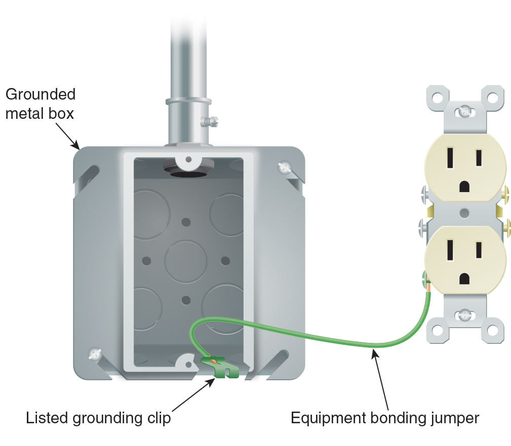
The following exhibits demonstrate two approved methods for attaching an equipment bonding jumper to a grounded metal box.
In the exhibit below, you can see an example of an equipment bonding jumper that has been installed from a grounded metal box to the equipment grounding terminal of a receptacle. This setup illustrates a compliant and safe method for ensuring effective grounding and bonding in electrical installations.

250.10 Protection of Ground Clamps and Fittings
250.10 Protection of Ground Clamps and Fittings.
Ground clamps or other fittings exposed to physical damage shall be enclosed in metal, wood, or equivalent protective covering.
250.12 Clean Surfaces
250.12 Clean Surfaces.
Nonconductive coatings (such as paint, lacquer, and enamel) on equipment to be grounded or bonded shall be removed from threads and other contact surfaces to ensure electrical continuity or shall be connected by means of fittings designed to make such removal unnecessary.
Enhanced Code Analysis:
250.12 Clean Surfaces: Some fittings, like locknuts and star washers, are specifically engineered to maintain strong electrical continuity with the contact surface, even through nonconductive coatings. The crucial aspect for the installer is to secure the connection tightly, guaranteeing that the locknut establishes a reliable electrical connection.
Part II. System Grounding
250.20 Alternating-Current Systems to Be Grounded.
Alternating-current systems shall be grounded in accordance with 250.20(A), (B), (C), or (D), unless prohibited elsewhere in this Code. Other systems shall be permitted to be grounded. If such systems are grounded, they shall comply with the applicable provisions of this article.
Informational Note No. 1: An example of a system permitted to be grounded is a corner-grounded delta transformer connection.
Informational Note No. 2: See 503.155, 517.61, 517.160, 668.10, and 680.23(A)(2) for examples of circuits prohibited to be grounded.
(A) Alternating-Current Systems of Less Than 50 Volts.
Alternating-current systems of less than 50 volts shall be grounded under any of the following conditions:
(1) If supplied by transformers, if the transformer supply system exceeds 150 volts to ground
(2) If supplied by transformers, if the transformer supply system is ungrounded
(3) If installed outside as overhead conductor
(B) Alternating-Current Systems of 50 Volts to 1000 Volts.
Alternating-current systems of 50 volts to 1000 volts that supply premises wiring and premises wiring systems shall be grounded under any of the following conditions:
(1) If the system can be grounded so that the maximum voltage to ground on the ungrounded conductors does not exceed 150 volts
(2) If the system is 3-phase, 4-wire, wye connected in which the neutral conductor is used as a circuit conductor
(3) If the system is 3-phase, 4-wire, delta connected in which the midpoint of one phase winding is used as a circuit conductor
Informational Note: See NFPA 70E-2021, Standard for Electrical Safety in the Workplace, Annex O, for information on impedance grounding to reduce arc-flash hazards.
(C) Alternating-Current Systems of over 1000 Volts.
Alternating-current systems supplying mobile or portable equipment shall be grounded in accordance with 250.188. If supplying other than mobile or portable equipment, such systems shall be permitted to be grounded.
![]() (D) Impedance Grounded Systems.
(D) Impedance Grounded Systems.
Impedance-grounded systems shall be grounded in accordance with 250.36 or 250.187, as applicable.
250.21 Alternating-Current Systems of 50 Volts to 1000 Volts Not Required to Be Grounded.
![]()
(A) General.
The following ac systems of 50 volts to 1000 volts shall be permitted to be grounded but shall not be required to be grounded:
(1) Electrical systems used exclusively to supply industrial electric furnaces used for applications such as melting, refining, or tempering
(2) Separately derived systems used exclusively for rectifiers that supply only adjustable-speed industrial drives
(3) Separately derived systems supplied by transformers that have a primary voltage rating of 1000 volts or less if all the following conditions are met:
a. The system is used exclusively for control circuits.
b. The conditions of maintenance and supervision ensure that only qualified persons service the installation.
c. Continuity of control power is required.
(4) Other systems that are not required to be grounded in accordance with 250.20(B)
(B) Ground Detectors.
Ground detectors shall be installed in accordance with the following:
(1) Ungrounded ac systems as permitted in 250.21(A)(1) through (A)(4) operating at not less than 120 volts and at 1000 volts or less shall have ground detectors installed on the system.
(2) The ground detection sensing equipment shall be connected as close as practicable to where the system receives its supply.
(C) Marking.
Ungrounded systems shall be legibly marked “Caution: Ungrounded System Operating — _____Volts Between Conductors” at the source or first disconnecting means of the system. The marking shall be of sufficient durability to withstand the environment involved.
250.24 Grounding of Service-Supplied Alternating-Current Systems.
(A) System Grounding Connections.
A premises wiring system supplied by a grounded ac service shall have a grounding electrode conductor connected to the grounded service conductor, at each service, in accordance with 250.24(A)(1) through (A)(4).
![]() (1) General.
(1) General.
The grounding electrode conductor connection shall be made at any accessible point from the load end of the overhead service conductors, service drop, underground service conductors, or service lateral to the terminal or bus to which the grounded service conductor is connected at the service disconnecting means.
Informational Note: See Article 100 for definitions of Service Conductors, Overhead; Service Conductors, Underground; Service Drop; and Service Lateral.
![]() (2) Outdoor Transformer.
(2) Outdoor Transformer.
If the transformer supplying the service is located outside the building, at least one additional grounding connection shall be made from the grounded service conductor to a grounding electrode, either at the transformer or elsewhere outside the building.
Exception: The additional grounding electrode conductor connection shall not be made on impedance grounded systems. Impedance grounded systems shall meet the requirements of 250.36 or 250.187, as applicable.
(3) Dual-Fed Services.
For services that are dual fed (double ended) in a common enclosure or grouped together in separate enclosures and employing a secondary tie, a single grounding electrode conductor connection to the tie point of the grounded conductor(s) from each power source shall be permitted.
(4) Main Bonding Jumper as Wire or Busbar.
If the main bonding jumper specified in 250.28 is a wire or busbar and is installed from the grounded conductor terminal bar or bus to the equipment grounding terminal bar or bus in the service equipment, the grounding electrode conductor shall be permitted to be connected to the equipment grounding terminal, bar, or bus to which the main bonding jumper is connected.
![]() (B) Load-Side Grounding Connections.
(B) Load-Side Grounding Connections.
A grounded conductor shall not be connected to normally non-current-carrying metal parts of equipment, to equipment grounding conductor(s), or be reconnected to ground on the load side of the service disconnecting means except as otherwise permitted in this article.
Informational Note: See 250.30 for separately derived systems, 250.32 for connections at separate buildings or structures, and 250.142 for use of the grounded circuit conductor for grounding equipment.
![]() (C) Main Bonding Jumper.
(C) Main Bonding Jumper.
For a grounded system, an unspliced main bonding jumper shall be used to connect the equipment grounding conductor(s) and the service-disconnect enclosure to the grounded conductor within the enclosure for each service disconnect in accordance with 250.28.
Exception No. 1: If more than one service disconnecting means is located in an assembly listed for use as service equipment, an unspliced main bonding jumper shall bond the grounded conductor(s) to the assembly enclosure.
Exception No. 2: Impedance grounded systems shall be permitted to be connected in accordance with 250.36 and 250.187.
(D) Grounded Conductor Brought to Service Equipment.
If an ac system operating at 1000 volts or less is grounded at any point, the grounded conductor(s) shall be routed with the ungrounded conductors to each service disconnecting means and shall be connected to each disconnecting means grounded conductor(s) terminal or bus. A main bonding jumper shall connect the grounded conductor(s) to each service disconnecting means enclosure. The grounded conductor(s) shall be installed in accordance with 250.24(D(1) through (D)(4).
Exception: If two or more service disconnecting means are located in a single assembly listed for use as service equipment, it shall be permitted to connect the grounded conductor(s) to the assembly common grounded conductor(s) terminal or bus. The assembly shall include a main bonding jumper for connecting the grounded conductor(s) to the assembly enclosure.
(1) Sizing for a Single Raceway or Cable.
The grounded conductor shall not be smaller than specified in Table 250.102(C)(1).
(2) Conductors Connected in Parallel in Two or More Raceways or Cables.
If the ungrounded service-entrance conductors are connected in parallel in two or more raceways or cables, the grounded conductors shall also be installed in each raceway or cable and shall be connected in parallel. The size of each grounded conductor(s) in each raceway or cable shall not be smaller than 1/0 AWG and shall be sized in accordance with 250.24(D)(2)(a) or (D)(2)(b) in accordance with 250.24(D)(1).
(a) Shall be based on the largest ungrounded conductor in each race way or cable.
(b) Shall be based on the sum of the circular mil areas of the largest ungrounded conductors from each set connected in parallel in each raceway or cable.
Informational Note: See 310.10(G) for grounded conductors connected in parallel.
(3) Delta-Connected Service.
The grounded conductor of a 3-phase, 3-wire delta service shall have an ampacity not less than that of the ungrounded conductors.
(4) Impedance Grounded Service.
The impedance grounding conductor on an impedance grounded system shall be connected in accordance with 250.36 or 250.187, as applicable.
(E) Grounding Electrode Conductor.
A grounding electrode conductor shall be used to connect the equipment grounding conductors, the service-equipment enclosures, and, if the system is grounded, the grounded service conductor to the grounding electrode(s) required by Part III of this article. This conductor shall be sized in accordance with 250.66.
impedance grounded system connections shall be made >mark>in accordance with 250.36 or 250.187, as applicable.
(F) Ungrounded System Grounding Connections.
A premises wiring system that is supplied by an ac service that is ungrounded shall have, at each service, a grounding electrode conductor connected to the grounding electrode(s) required by Part III of this article. The grounding electrode conductor shall be connected to a metal enclosure of the service conductors at any accessible point from the load end of the overhead service conductors, service drop, underground service conductors, or service lateral to the service disconnecting means.
250.25 Grounding of Systems Permitted to Be Connected on the Supply Side of the Service Disconnect.
The grounding of systems connected on the supply side of the service disconnect, in accordance with 230.82, that are in enclosures separate from the service equipment enclosure shall comply with 250.25(A) or (B).
(A) Grounded System.
If the utility supply system is grounded, the grounding of systems permitted to be connected on the supply side of the service disconnect and are installed in one or more separate enclosures from the service equipment enclosure shall comply with the requirements of 250.24(A) through (D).
(B) Ungrounded Systems.
If the utility supply system is ungrounded, the grounding of systems permitted to be connected on the supply side of the service disconnect and are installed in one or more separate enclosures from the service equipment enclosure shall comply with the requirements of 250.24(F).
250.26 Conductor to Be Grounded — Alternating-Current Systems.
If an ac premises wiring system is grounded, the conductor to be grounded shall be one of the following:
(1) Single-phase, 2-wire — one conductor
(2) Single-phase, 3-wire — the neutral conductor
(3) Multiphase systems having one wire common to all phases — the neutral conductor
(4) Multiphase systems if one phase is grounded — that phase conductor
(5) Multiphase systems in which one phase is used as in (2) — the neutral conductor
50.28 Main Bonding Jumper and System Bonding Jumper.
For a grounded system, main bonding jumpers and system bonding jumpers shall be installed as follows:
(A) Material.
Main bonding jumpers and system bonding jumpers shall be of copper, aluminum, copper-clad aluminum, or other corrosion-resistant material. A main bonding jumper and a system bonding jumper shall be a wire, bus, screw, or similar suitable conductor.
(B) Construction.
if a main bonding jumper or a system bonding jumper is a screw only, the screw shall be identified with a green finish that shall be visible with the screw installed.
(C) Attachment.
Main bonding jumpers and system bonding jumpers shall be connected by one or more of the methods in 250.8 that is suitable for the material of the bonding jumper and enclosure.
(D) Size.
Main bonding jumpers and system bonding jumpers shall be sized in accordance with 250.28(D)(1) through (D)(3).
(1) General.
Main bonding jumpers and system bonding jumpers shall not be smaller than specified in Table 250.102(C)(1).
(2) Main Bonding Jumper for Service with More Than One Enclosure.
If a service consists of more than a single enclosure as permitted in 230.71(B), the main bonding jumper for each enclosure shall be sized in accordance with 250.28(D)(1) based on the largest ungrounded service conductor serving that enclosure.
(3) Separately Derived System with More Than One Enclosure.
if a separately derived system supplies more than a single enclosure, the system bonding jumper for each enclosure shall be sized in accordance with 250.28(D)(1) based on the largest ungrounded feeder conductor serving that enclosure, or a single system bonding jumper shall be installed at the source and sized in accordance with 250.28(D)(1) based on the equivalent size of the largest supply conductor determined by the largest sum of the areas of the corresponding conductors of each set.
250.30 Grounding Separately Derived Alternating-Current Systems.
In addition to complying with 250.30(A) for grounded systems, or as provided in 250.30(B) for ungrounded systems, separately derived systems shall comply with 250.20, 250.21, or 250.26, as applicable. Multiple power sources of the same type that are connected in parallel to form one system that supplies premises wiring shall be treated as a single separately derived system and shall be installed in accordance with 250.30.
Informational Note No. 1: An alternate ac power source, such as an on-site generator, is not a separately derived system if the grounded conductor is solidly interconnected to a service-supplied system grounded conductor. An example of such a situation is if the alternate source transfer equipment does not include a switching action in the grounded conductor and allows it to remain solidly connected to the service-supplied grounded conductor when the alternate source is operational and supplying the load served.
Informational Note No. 2: See 445.13 for the minimum size of conductors that carry fault current.
![]() (A) Grounded Systems.
(A) Grounded Systems.
A separately derived ac system that is grounded shall comply with 250.30(A)(1) through (A)(8). Except as otherwise permitted in this article, a grounded conductor shall not be connected to normally non-current-carrying metal parts of equipment, be connected to equipment grounding conductors, or be reconnected to ground on the load side of the system bonding jumper.
Informational Note: See 250.32 for connections at separate buildings or structures and 250.142 for use of the grounded circuit conductor for grounding equipment.
Exception: Impedance grounded system grounding connections shall be made in accordance with 250.36 or 250.187, as applicable.
(1) System Bonding Jumper.
An unspliced system bonding jumper shall comply with 250.28(A) through (D). This connection shall be made at any single point on the separately derived system from the source to the first system disconnecting means or overcurrent device, or it shall be made at the source of a separately derived system that has no disconnecting means or overcurrent devices, in accordance with 250.30(A)(1)(a) or (A)(1)(b). The system bonding jumper shall remain within the enclosure where it originates. If the source is located outside the building or structure supplied, a system bonding jumper shall be installed at the grounding electrode connection in compliance with 250.30(C).
Exception No. 1: For systems installed in accordance with 450.6, a single system bonding jumper connection to the tie point of the grounded circuit conductors from each power source shall be permitted.
Exception No. 2: If a building or structure is supplied by a feeder from an outdoor separately derived system, a system bonding jumper at both the source and the first disconnecting means shall be permitted if doing so does not establish a parallel path for the grounded conductor. If a grounded conductor is used in this manner, it shall not be smaller than the size specified for the system bonding jumper but shall not be required to be larger than the ungrounded conductor(s). For the purposes of this exception, connection through the earth shall not be considered as providing a parallel path.
Exception No. 3: The size of the system bonding jumper for a system that supplies a Class 1, Class 2, or Class 3 circuit, and is derived from a transformer rated not more than 1000 volt-amperes, shall not be smaller than the derived ungrounded conductors and shall not be smaller than 14 AWG copper or 12 AWG aluminum.
(a) Installed at the Source. The system bonding jumper shall connect the grounded conductor to the supply-side bonding jumper and the normally non-current-carrying metal enclosure.
(b) Installed at the First Disconnecting Means. The system bonding jumper shall connect the grounded conductor to the supply-side bonding jumper, the disconnecting means enclosure, and the equipment grounding conductor(s).
Exception: Separately derived systems consisting of multiple sources of the same type that are connected in parallel shall be permitted to have the system bonding jumper installed at the paralleling switchgear, switchboard, or other paralleling connection point instead of at the disconnecting means located at each separate source.
(2) Supply-Side Bonding Jumper.
If the source of a separately derived system and the first disconnecting means are located in separate enclosures, a supply-side bonding jumper shall be installed with the circuit conductors from the source enclosure to the first disconnecting means enclosure. A supply-side bonding jumper shall not be required to be larger than the derived ungrounded conductors. The supply-side bonding jumper shall be permitted to be of nonflexible metal raceway type or of the wire or bus type as follows:
(1) A supply-side bonding jumper of the wire type shall comply with 250.102(C), based on the size of the derived ungrounded conductors.
(2) A supply-side bonding jumper of the bus type shall have a cross-sectional area not smaller than a supply-side bonding jumper of the wire type as determined in 250.102(C).
Exception: A supply-side bonding jumper shall not be required between enclosures for installations made in compliance with 250.30(A)(1), Exception No. 2.
![]() (3) Grounded Conductor.
(3) Grounded Conductor.
If a grounded conductor is installed and the system bonding jumper connection is not located at the source, 250.30(A)(3)(a) through (A)(3)(d) shall apply. The grounded conductor shall not be required to be larger than the derived ungrounded conductors.
(a) Sizing for a Single Raceway. The grounded conductor shall not be smaller than specified in Table 250.102(C)(1).
(b) Conductors Connected in Parallel in Two or More Raceways or Cables. If the ungrounded conductors are connected in parallel in two or more raceways or cables, the grounded conductors shall also be installed in each raceway or cable and shall be connected in parallel. The size of the grounded conductor(s) in each raceway or cable shall be based on the largest derived ungrounded conductor in each raceway or cable, or the sum of the circular mil areas of the largest derived ungrounded conductors from each set connected in parallel in each raceway or cable, in accordance with 250.30(A)(3)(a), but not smaller than 1/0 AWG.
Informational Note: See 310.10(G) for grounded conductors connected in parallel.
(c) Delta-Connected System. The grounded conductor of a 3-phase, 3-wire delta system shall have an ampacity not less than that of the ungrounded conductors.
(d) Impedance Grounded System. The impedance grounding conductor of an impedance grounded system shall be installed in accordance with 250.36 or 250.187, as applicable.
(4) Grounding Electrode.
The building or structure grounding electrode system shall be used as the grounding electrode for the separately derived system. If located outdoors, the grounding electrode shall be in accordance with 250.30(C).
Exception: If a separately derived system originates in equipment that is listed and identified as suitable for use as service equipment, the grounding electrode used for the service or feeder equipment shall be permitted to be used as the grounding electrode for the separately derived system.
Informational Note No. 1: See 250.104(D) for bonding requirements for interior metal water piping in the area served by separately derived systems.
Informational Note No. 2: See 250.50 and 250.58 for requirements for bonding all electrodes together if located at the same building or structure.
(5) Grounding Electrode Conductor, Single Separately Derived System.
A grounding electrode conductor for a single separately derived system shall be sized in accordance with 250.66 for the derived ungrounded conductors. It shall be used to connect the grounded conductor of the derived system to the grounding electrode in accordance with 250.30(A)(4), or as permitted in 250.68(C)(1) and (C)(2). This connection shall be made at the same point on the separately derived system where the system bonding jumper is connected.
Exception No. 1: If the system bonding jumper specified in 250.30(A)(1) is a wire or busbar, it shall be permitted to connect the grounding electrode conductor to the equipment grounding terminal, bar, or bus if the equipment grounding terminal, bar, or bus is of sufficient size for the separately derived system.
Exception No. 2: If the source of a separately derived system is located within equipment listed and identified as suitable for use as service equipment, the grounding electrode conductor from the service or feeder equipment to the grounding electrode shall be permitted as the grounding electrode conductor for the separately derived system, if the grounding electrode conductor is of sufficient size for the separately derived system. If the equipment grounding bus internal to the equipment is not smaller than the required grounding electrode conductor for the separately derived system, the grounding electrode connection for the separately derived system shall be permitted to be made to the bus.
Exception No. 3: A grounding electrode conductor shall not be required for a system that supplies a Class 1, Class 2, or Class 3 circuit and is derived from a transformer rated not more than 1000 volt-amperes, provided the grounded conductor is bonded to the transformer frame or enclosure by a jumper sized in accordance with 250.30(A)(1), Exception No. 3, and the transformer frame or enclosure is grounded by one of the means specified in 250.134.
(6) Grounding Electrode Conductor, Multiple Separately Derived Systems.
A common grounding electrode conductor for multiple separately derived systems shall be permitted. If installed, the common grounding electrode conductor shall be used to connect the grounded conductor of each separately derived system to the grounding electrode as specified in 250.30(A)(4). A grounding electrode conductor tap shall then be installed from each separately derived system to the common grounding electrode conductor. Each tap conductor shall connect the grounded conductor of the separately derived system to the common grounding electrode conductor. This connection shall be made at the same point on the separately derived system where the system bonding jumper is connected.
Exception No. 1: If the system bonding jumper specified in 250.30(A)(1) is a wire or busbar, it shall be permitted to connect the grounding electrode conductor tap to the equipment grounding terminal, bar, or bus, provided the equipment grounding terminal, bar, or bus is of sufficient size for the separately derived system.
Exception No. 2: A grounding electrode conductor shall not be required for a system that supplies a Class 1, Class 2, or Class 3 circuit and is derived from a transformer rated not more than 1000 volt-amperes, provided the system grounded conductor is bonded to the transformer frame or enclosure by a jumper sized in accordance with 250.30(A)(1), Exception No. 3, and the transformer frame or enclosure is grounded by one of the means specified in 250.134.
Exception No. 3: If the source of a separately derived system is located within equipment listed and identified as suitable for use as service equipment, the grounding electrode conductor from the service or feeder equipment to the grounding electrode shall be permitted as the grounding electrode conductor for the separately derived system, if the grounding electrode conductor is of sufficient size for the separately derived system. If the equipment grounding bus internal to the equipment is not smaller than the required grounding electrode conductor for the separately derived system, the grounding electrode connection for the separately derived system shall be permitted to be made to the bus.
(a) Common Grounding Electrode Conductor. The common grounding electrode conductor shall be permitted to be one of the following:
(1) A conductor of the wire type not smaller than 3/0 AWG copper or 250 kcmil aluminum
(2) A metal water pipe in accordance with 250.68(C)(1)
(3)The metal structural frame of the building or structure in accordance with 250.68(C)(2) or is connected to the grounding electrode system by a conductor not smaller than 3/0 AWG copper or 250 kcmil aluminum
(b) Tap Conductor Size. Each tap conductor shall be sized in accordance with 250.66 based on the derived ungrounded conductors of the separately derived system it serves.
Exception to (a)(1) and (b): If the only electrodes that are present are of the types in 250.66(A), (B), or (C), the size of the common grounding electrode conductor shall not be required to be larger than the largest conductor required by 250.66(A), (B), or (C) for the type of electrode that is present.
(c) Connections. All tap connections to the common grounding electrode conductor shall be made at an accessible location by one of the following methods:
(1) A connector listed as grounding and bonding equipment.
(2) Listed connections to aluminum or copper busbars not smaller than 6 mm thick × 50 mm wide (1⁄4 in. thick × 2 in. wide) and of a length to accommodate the number of terminations necessary for the installation. If aluminum busbars are used, the installation shall also be in accordance with 250.64(A).
(3) The exothermic welding process.
Tap conductors shall be connected to the common grounding electrode conductor in such a manner that the common grounding electrode conductor remains without a splice or joint.
(7) Installation.
The installation of all grounding electrode conductors shall comply with 250.64(A), (B), (C), and (E).
(8) Bonding.
Structural steel and metal piping shall be connected to the grounded conductor of a separately derived system in accordance with 250.104(D).
(B) Ungrounded Systems.
The equipment of an ungrounded separately derived system shall be grounded and bonded as specified in 250.30(B)(1) through (B)(3).
(1) Grounding Electrode Conductor.
A grounding electrode conductor, sized in accordance with 250.66 for the largest derived ungrounded conductor(s) or set of derived ungrounded conductors, shall be used to connect the metal enclosures of the derived system to the grounding electrode as specified in 250.30(A)(5) or (A)(6), as applicable. This connection shall be made at any point on the separately derived system from the source to the first system disconnecting means. If the source is located outside the building or structure supplied, a grounding electrode connection shall be made in compliance with 250.30(C).
(2) Grounding Electrode.
Except as permitted by 250.34 for portable and vehicle-mounted generators, the grounding electrode shall comply with 250.30(A)(4).
(3) Bonding Path and Conductor.
A supply-side bonding jumper shall be installed from the source of a separately derived system to the first disconnecting means in compliance with 250.30(A)(2).
(C) Outdoor Source.
If the source of the separately derived system is located outside the building or structure supplied, a grounding electrode connection shall be made at the source location to one or more grounding electrodes in accordance with 250.50. In addition, the installation shall be in accordance with 250.30(A) for grounded systems or with 250.30(B) for ungrounded systems.
Exception: The grounding electrode conductor connection for impedance-grounded systems shall be in accordance with 250.36 or 250.187, as applicable.
250.32 Buildings or Structures Supplied by a Feeder(s) or Branch Circuit(s).
(A) Grounding Electrode System and Grounding Electrode Conductor.
A building(s) or structure(s) supplied by a feeder(s) or branch circuit(s) shall have a grounding electrode system and grounding electrode conductor installed in accordance with Part III of Article 250.
Exception: A grounding electrode system and grounding electrode conductor shall not be required if only a single branch circuit, including a multiwire branch circuit, supplies the building or structure and the branch circuit includes an equipment grounding conductor for grounding the normally non-current-carrying metal parts of equipment.
(B) Grounded Systems.
(1) Supplied by a Feeder or Branch Circuit.
An equipment grounding conductor, as described in 250.118, shall be run with the supply conductors and be connected to the building or structure disconnecting means and to the grounding electrode(s). The equipment grounding conductor shall be used for grounding or bonding of equipment, structures, or frames required to be grounded or bonded. The equipment grounding conductor shall be sized in accordance with 250.122. Any installed grounded conductor shall not be connected to the equipment grounding conductor or to the grounding electrode(s).
Exception No. 1: For installations made in compliance with previous editions of this Code that permitted such connection, the grounded conductor run with the supply to the building or structure shall be permitted to serve as the ground-fault return path if all of the following requirements continue to be met:
(1) An equipment grounding conductor is not run with the supply to the building or structure.
(2) There are no continuous metallic paths bonded to the grounding system in each building or structure involved.
(3) Ground-fault protection of equipment has not been installed on the supply side of the feeder(s).
If the grounded conductor is used for grounding in accordance with the provision of this exception, the size of the grounded conductor shall not be smaller than the larger of either of the following:
(1) The calculated neutral load in accordance with 220.61
(2) The minimum equipment grounding conductor sized in accordance with 250.122
Exception No. 2: If system bonding jumpers are installed in accordance with 250.30(A)(1), Exception No. 2, the feeder grounded circuit conductor at the building or structure served shall be connected to the equipment grounding conductors, grounding electrode conductor, and the enclosure for the first disconnecting means.
(2) Supplied by Separately Derived System.
(a) With Overcurrent Protection. If overcurrent protection is provided where the conductors originate, the installation shall comply with 250.32(B)(1).
(b) Without Overcurrent Protection. If overcurrent protection is not provided where the conductors originate, the installation shall comply with 250.30(A). If installed, the supply-side bonding jumper shall be connected to the building or structure disconnecting means and to the grounding electrode(s).
(C) Ungrounded Systems.
(1) Supplied by a Feeder or Branch Circuit.
An equipment grounding conductor, as described in 250.118, shall be installed with the supply conductors and be connected to the building or structure disconnecting means and to the grounding electrode(s). The grounding electrode(s) shall also be connected to the building or structure disconnecting means.
(2) Supplied by a Separately Derived System.
(a) With Overcurrent Protection. If overcurrent protection is provided where the conductors originate, the installation shall comply with 250.32(C)(1).
(b) Without Overcurrent Protection. If overcurrent protection is not provided where the conductors originate, the installation shall comply with 250.30(B). If installed, the supply-side bonding jumper shall be connected to the building or structure disconnecting means and to the grounding electrode(s).
(D) Disconnecting Means Located in Separate Building or Structure on the Same Premises.
If one or more disconnecting means supply one or more additional buildings or structures under single management, and where these disconnecting means are located remote from those buildings or structures in accordance with 225.31(B), Exception No. 1 and No. 2, 700.12(D)(4), 701.12(D)(3), or 702.12, all of the following conditions shall be met:
(1) The connection of the grounded conductor to the grounding electrode, to normally non-current-carrying metal parts of equipment, or to the equipment grounding conductor at a separate building or structure shall not be made.
(2) An equipment grounding conductor for grounding and bonding any normally non-current-carrying metal parts of equipment, interior metal piping systems, and building or structural metal frames is run with the circuit conductors to a separate building or structure and connected to existing grounding electrode(s) required in Part III of this article, or, if there are no existing electrodes, the grounding electrode(s) required in Part III of this article shall be installed if a separate building or structure is supplied by more than one branch circuit.
(3) The connection between the equipment grounding conductor and the grounding electrode at a separate building or structure shall be made in a junction box, panelboard, or similar enclosure located immediately inside or outside the separate building or structure.
(E) Grounding Electrode Conductor.
The size of the grounding electrode conductor to the grounding electrode(s) shall not be smaller than given in 250.66, based on the largest ungrounded supply conductor. The installation shall comply with Part III of this article.
250.34 Portable, Vehicle-Mounted, and Trailer-Mounted Generators.
(A) Portable Generators.
The frame of a portable generator shall not be required to be connected to a grounding electrode as defined in 250.52 for a system supplied by the generator under both of the following conditions:
(1) The generator supplies only equipment mounted on the generator, cord-and-plug-connected equipment through receptacles mounted on the generator, or both.
(2) The normally non-current-carrying metal parts of equipment and the equipment grounding conductor terminals of the receptacles are connected to the generator frame.
(B) Vehicle-Mounted and Trailer-Mounted Generators.
The frame of a vehicle or trailer shall not be required to be connected to a grounding electrode as defined in 250.52 for a system supplied by a generator located on this vehicle or trailer under all of the following conditions:
(1) The frame of the generator is bonded to the vehicle or trailer frame.
(2) The generator supplies only equipment located on the vehicle or trailer; cord-and-plug-connected equipment through receptacles mounted on the vehicle; or both equipment located on the vehicle or trailer and cord-and-plug-connected equipment through receptacles mounted on the vehicle, trailer, or on the generator.
(3) The normally non-current-carrying metal parts of equipment and the equipment grounding conductor terminals of the receptacles are connected to the generator frame.
(C) Grounded Conductor Bonding.
A conductor that is required to be grounded by 250.26 shall be connected to the generator frame if the generator is a component of a separately derived system.
Informational Note: See 250.30 for grounding portable generators supplying fixed wiring systems.
250.35 Permanently Installed Generators.
A conductor that provides an effective ground-fault current path shall be installed with the supply conductors from a permanently installed generator(s) to the first disconnecting mean(s) in accordance with 250.35(A) or (B).
(A) Separately Derived System.
If the generator is installed as a separately derived system, the requirements in 250.30 shall apply.
(B) Nonseparately Derived System.
If the generator is installed as a nonseparately derived system, and overcurrent protection is not integral with the generator assembly, a supply-side bonding jumper shall be installed between the generator equipment grounding terminal and the equipment grounding terminal, bar, or bus of the disconnecting mean(s). It shall be sized in accordance with 250.102(C) based on the size of the conductors supplied by the generator.
250.36 Impedance Grounded Systems — 480 Volts to 1000 Volts.
Impedance grounded systems in which a grounding impedance device, typically a resistor, limits the ground-fault current shall be permitted for 3-phase ac systems of 480 volts to 1000 volts if all the following conditions are met:
(1) The conditions of maintenance and supervision ensure that only qualified persons service the installation.
(2) Ground detectors are installed on the system.
(3) Line-to-neutral loads are not served.
Impedance grounded systems shall comply with 250.36(A) through (G).
Informational Note: See NFPA 70E-2021, Standard for Electrical Safety in the Workplace, Annex O, for information on impedance grounding to reduce arc-flash hazards.
(A) Location.
The grounding impedance device shall be installed between the grounding electrode conductor and the impedance grounding conductor connected to the system neutral point. If a neutral point is not available, the grounding impedance shall be installed between the grounding electrode conductor and the impedance grounding conductor connected to the neutral point derived from a grounding transformer.
(B) Impedance Grounding Conductor Insulation and Ampacity.
The impedance grounding conductor from the neutral point of the transformer or generator to its connection point to the grounding impedance shall be fully insulated.
The impedance grounding conductor shall have an ampacity of not less than the maximum current rating of the grounding impedance but in no case shall the impedance grounding conductor be smaller than 8 AWG copper or 6 AWG aluminum or copper-clad aluminum.
(C) System Grounding Connection.
The system shall not be connected to ground except through the grounding impedance device.
Informational Note: The impedance is normally selected to limit the ground-fault current to a value slightly greater than or equal to the capacitive charging current of the system. This value of impedance will also limit transient overvoltages to safe values. For guidance, refer to criteria for limiting transient overvoltages in IEEE 3003.1-2019, Recommended Practice for System Grounding of Industrial and Commercial Power Systems.
(D) Impedance Grounding Conductor Routing.
The impedance grounding conductor shall be permitted to be installed in a separate raceway from the ungrounded conductors. It shall not be required to run this conductor with the phase conductors to the first system disconnecting means or overcurrent device.
(E) Impedance Bonding Jumper.
The impedance bonding jumper (the connection between the equipment grounding conductors and the grounding impedance device) shall be an unspliced conductor run from the first system disconnecting means or overcurrent device to the grounded side of the grounding impedance device.
(F) Grounding Electrode Conductor Connection Location.
For services or separately derived systems, the grounding electrode conductor shall be connected at any point from the grounded side of the grounding impedance device to the equipment grounding connection at the service equipment or the first system disconnecting means of a separately derived system.
(G) Impedance Bonding Jumper Size.
The impedance bonding jumper shall be sized in accordance with either of the following:
(1) If the grounding electrode conductor connection is made at the grounding impedance device, the equipment bonding jumper shall be sized in accordance with 250.66, based on the size of the service entrance conductors for a service or the derived phase conductors for a separately derived system.
(2) If the grounding electrode conductor is connected at the first system disconnecting means or overcurrent device, the impedance bonding jumper shall be sized the same as the impedance grounding conductor in 250.36(B).
Part III. Grounding Electrode System and Grounding Electrode Conductor
250.50 Grounding Electrode System.
All grounding electrodes as described in 250.52(A)(1) through (A)(7) that are present at each building or structure served shall be bonded together to form the grounding electrode system. If none of these grounding electrodes exist, one or more of the grounding electrodes specified in 250.52(A)(4) through (A)(8) shall be installed and used.
Exception: Concrete-encased electrodes of existing buildings or structures shall not be required to be part of the grounding electrode system if the rebar is not accessible for use without disturbing the concrete.
250.52 Grounding Electrodes.
(A) Electrodes Permitted for Grounding.
(1) Metal Underground Water Pipe.
A metal underground water pipe in direct contact with the earth for 3.0 m (10 ft) or more (including any metal well casing bonded to the pipe) and electrically continuous (or made electrically continuous by bonding around insulating joints or insulating pipe) to the points of connection of the grounding electrode conductor and the bonding conductor(s) or jumper(s), if installed.
(2) Metal In-ground Support Structure(s).
One or more metal in-ground support structure(s) in direct contact with the earth vertically for 3.0 m (10 ft) or more, with or without concrete encasement. If multiple metal in-ground support structures are present at a building or a structure, it shall be permissible to bond only one into the grounding electrode system.
Informational Note: Metal in-ground support structures include, but are not limited to, pilings, casings, and other structural metal.
(3) Concrete-Encased Electrode.
A concrete-encased electrode shall consist of at least 6.0 m (20 ft) of either of the following:
(1) One or more bare or zinc galvanized or other electrically conductive coated rebar of not less than 13 mm (1⁄2 in.) in diameter, installed in one continuous 6.0 m (20 ft) length, or if in multiple pieces, the rebar shall be connected together by steel tie wires, exothermic welding, welding, or other effective means to create a 6.0 m (20 ft) or greater length
(2) Bare copper conductor not smaller than 4 AWG
Metal components shall be encased by at least 50 mm (2 in.) of concrete and shall be located horizontally within that portion of a concrete foundation or footing that is in direct contact with the earth or within vertical foundations or structural components or members that are in direct contact with the earth. If multiple concrete-encased electrodes are present at a building or structure, it shall be permissible to bond only one into the grounding electrode system.
Informational Note: Concrete installed with insulation, vapor barriers, films, or similar items separating the concrete from the earth is not considered to be in “direct contact” with the earth.
(4) Ground Ring.
A ground ring encircling the building or structure, in direct contact with the earth, consisting of at least 6.0 m (20 ft) of bare copper conductor not smaller than 2 AWG.
(5) Rod and Pipe Electrodes.
Rod and pipe electrodes shall not be less than 2.44 m (8 ft) in length and consist of the following materials.
(1) Grounding electrodes of pipe or conduit shall not be smaller than metric designator 21 (trade size 3⁄4) and, where of steel, shall have the outer surface galvanized or otherwise metal-coated for corrosion protection.
(2) Rod-type grounding electrodes of stainless steel and copper or zinc-coated steel shall be at least 15.87 mm (5⁄8 in.) in diameter, unless listed.
(6) Other Listed Electrodes.
Other listed grounding electrodes shall be permitted.
(7) Plate Electrodes.
Each plate electrode shall expose not less than 0.186 m2 (2 ft2) of surface to exterior soil. Electrodes of bare or electrically conductive coated iron or steel plates shall be at least 6.4 mm (1⁄4 in.) in thickness. Solid, uncoated electrodes of nonferrous metal shall be at least 1.5 mm (0.06 in.) in thickness.
(8) Other Local Metal Underground Systems or Structures.
Other local metal underground systems or structures such as piping systems, underground tanks, and underground metal well casings that are not bonded to a metal water pipe.
(B) Not Permitted for Use as Grounding Electrodes.
The following systems and materials shall not be used as grounding electrodes:
(1) Metal underground gas piping systems
(2) Aluminum
(3) The structures and structural rebar described in 680.26(B)(1) and (B)(2)
Informational Note: See 250.104(B) for bonding requirements of gas piping.
250.53 Grounding Electrode System Installation.
(A) Rod, Pipe, and Plate Electrodes.
Rod, pipe, and plate electrodes shall be free from nonconductive coatings such as paint or enamel. Rod, pipe, and plate electrodes shall meet the requirements of 250.53(A)(1) through (A)(3).
(1) Below Permanent Moisture Level.
If practicable, rod, pipe, and plate electrodes shall be embedded below permanent moisture level.
(2) Supplemental Electrode Required.
A single rod, pipe, or plate electrode shall be supplemented by an additional electrode of a type specified in 250.52(A)(2) through (A)(8). The supplemental electrode shall be permitted to be bonded to one of the following:
(1) Rod, pipe, or plate electrode
(2) Grounding electrode conductor
(3) Grounded service-entrance conductor
(4) Nonflexible grounded service raceway
(5) Any grounded service enclosure
Exception: If a single rod, pipe, or plate grounding electrode has a resistance to earth of 25 ohms or less, the supplemental electrode shall not be required.
(3) Supplemental Electrode.
If multiple rod, pipe, or plate electrodes are installed to meet the requirements of this section, they shall not be less than 1.8 m (6 ft) apart.
Informational Note: The paralleling efficiency of rods is increased by spacing them twice the length of the longest rod.
(4) Rod and Pipe Electrodes.
The electrode shall be installed such that at least 2.44 m (8 ft) of length is in contact with the soil. It shall be driven to a depth of not less than 2.44 m (8 ft) except that, where rock bottom is encountered, the electrode shall be driven at an oblique angle not to exceed 45 degrees from the vertical or, where rock bottom is encountered at an angle up to 45 degrees, the electrode shall be permitted to be buried in a trench that is at least 750 mm (30 in.) deep. The upper end of the electrode shall be flush with or below ground level unless the aboveground end and the grounding electrode conductor attachment are protected against physical damage as specified in 250.10.
(5) Plate Electrode.
Plate electrodes shall be installed not less than 750 mm (30 in.) below the surface of the earth.
(B) Electrode Spacing.
If more than one of the electrodes of the type specified in 250.52(A)(5) or (A)(7) are used, each electrode of one grounding system (including that used for strike termination devices) shall not be less than 1.83 m (6 ft) from any other electrode of another grounding system.
(C) Bonding Jumper.
The bonding jumper(s) used to connect the grounding electrodes together to form the grounding electrode system shall be installed in accordance with 250.64(A), (B), and (E), shall be sized in accordance with 250.66, and shall be connected in the manner specified in 250.70. Rebar shall not be used as a conductor to interconnect the electrodes of grounding electrode systems.
(D) Metal Underground Water Pipe.
If used as a grounding electrode, metal underground water pipe shall meet the requirements of 250.53(D)(1) and (D)(2).
(1) Continuity.
Continuity of the grounding path or the bonding connection to interior piping shall not rely on water meters or filtering devices and similar equipment.
(2) Supplemental Electrode Required.
A metal underground water pipe shall be supplemented by an additional electrode of a type specified in 250.52(A)(2) through (A)(8). If the supplemental electrode is of the rod, pipe, or plate type, it shall comply with 250.53(A). The supplemental electrode shall be bonded to one of the following:
(1) Grounding electrode conductor
(2) Grounded service-entrance conductor
(3) Nonflexible grounded service raceway
(4) Any grounded service enclosure
(5) As provided by 250.32(B)
Exception: The supplemental electrode shall be permitted to be bonded to the interior metal water piping as specified in 250.68(C)(1).
(E) Supplemental Grounding Electrode Bonding Jumper Size.
If the supplemental electrode is a rod, pipe, or plate electrode, that portion of the bonding jumper that is the sole connection to the supplemental grounding electrode shall not be required to be larger than 6 AWG copper wire or 4 AWG aluminum or copper-clad aluminum wire.
(F) Ground Ring.
The ground ring shall be installed not less than 750 mm (30 in.) below the surface of the earth.
250.54 Auxiliary Grounding Electrodes.
250.58 Common Grounding Electrode.
250.60 Use of Strike Termination Devices.
250.62 Grounding Electrode Conductor Material.
The grounding electrode conductor shall be of copper, aluminum, copper-clad aluminum, or the items as permitted in 250.68(C). The material selected shall be resistant to any corrosive condition existing at the installation or shall be protected against corrosion. Conductors of the wire type shall be solid or stranded, insulated, covered, or bare.
250.64 Grounding Electrode Conductor Installation.
Grounding electrode conductors at the service, at each building or structure where supplied by a feeder(s) or branch circuit(s), or at a separately derived system shall be installed as specified in 250.64(A) through (G).
(A) Aluminum or Copper-Clad Aluminum Conductors.
Grounding electrode conductors of bare, covered, or insulated aluminum or copper-clad aluminum shall comply with the following:
(1) Bare or covered conductors without an extruded polymeric covering shall not be installed where subject to corrosive conditions or be installed in direct contact with concrete.
(2) Terminations made within outdoor enclosures that are listed and identified for the environment shall be permitted within 450 mm (18 in.) of the bottom of the enclosure.
(3) Aluminum or copper-clad aluminum conductors external to buildings or equipment enclosures shall not be terminated within 450 mm (18 in.) of the earth.
(B) Securing and Protection Against Physical Damage.
If exposed, a grounding electrode conductor or its enclosure shall be securely fastened to the surface on which it is carried. Grounding electrode conductors shall be permitted to be installed on or through framing members.
(1) Not Exposed to Physical Damage.
A 6 AWG or larger copper, copper-clad aluminum, or aluminum grounding electrode conductor not exposed to physical damage shall be permitted to be run along the surface of the building construction without metal covering or protection.
(2) Exposed to Physical Damage.
A 6 AWG or larger copper, copper-clad aluminum, or aluminum grounding electrode conductor exposed to physical damage shall be protected in rigid metal conduit (RMC), intermediate metal conduit (IMC), Schedule 80 rigid polyvinyl chloride conduit (PVC), reinforced thermosetting resin conduit Type XW (RTRC-XW), electrical metallic tubing (EMT), or cable armor.
(3) Smaller Than 6 AWG.
Grounding electrode conductors smaller than 6 AWG shall be protected in RMC, IMC, Schedule 80 PVC, RTRC-XW, EMT, or cable armor.
(4) In Contact with the Earth.
Grounding electrode conductors and grounding electrode bonding jumpers in contact with the earth shall not be required to comply with 300.5 or 305.15, but shall be buried or otherwise protected if subject to physical damage.
(C) Continuous.
Except as provided in 250.30(A)(5) and (A)(6), 250.30(B)(1), and 250.68(C), grounding electrode conductor(s) shall be installed in one continuous length without a splice or joint. If necessary, splices or connections shall be made as permitted in the following:
(1) Splicing of the wire-type grounding electrode conductor shall be permitted only by irreversible compression-type connectors listed as grounding and bonding equipment or by the exothermic welding process.
(2) Sections of busbars shall be permitted to be connected together to form a grounding electrode conductor.
(3) Bolted, riveted, or welded connections of structural metal frames of buildings or structures.
(4) Threaded, welded, brazed, soldered or bolted-flange connections of metal water piping.
(D) Building or Structure with Multiple Disconnecting Means in Separate Enclosures.
If a building or structure is supplied by a service or feeder with two or more disconnecting means in separate enclosures, the grounding electrode connections shall be made in accordance with 250.64(D)(1), (D)(2), or (D)(3).
(1) Common Grounding Electrode Conductor and Taps.
A common grounding electrode conductor and grounding electrode conductor taps shall be installed. The common grounding electrode conductor shall be sized in accordance with 250.66, based on the sum of the circular mil area of the largest ungrounded conductor(s) of each set of conductors that supplies the disconnecting means. If the service-entrance conductors connect directly to the overhead service conductors, service drop, underground service conductors, or service lateral, the common grounding electrode conductor shall be sized in accordance with Table 250.66, note 1.
A grounding electrode conductor tap shall extend to the inside of each disconnecting means enclosure. The grounding electrode conductor taps shall be sized in accordance with 250.66 for the largest service-entrance or feeder conductor serving the individual enclosure. The tap conductors shall be connected to the common grounding electrode conductor by one of the following methods in such a manner that the common grounding electrode conductor remains without a splice or joint:
(1) Exothermic welding.
(2) Connectors listed as grounding and bonding equipment.
(3) Connections to an aluminum or copper busbar not less than 6 mm thick × 50 mm wide (1⁄4 in. thick × 2 in. wide) and of a length to accommodate the number of terminations necessary for the installation. The busbar shall be securely fastened and shall be installed in an accessible location. Connections shall be made by a listed connector or by the exothermic welding process. If aluminum busbars are used, the installation shall comply with 250.64(A).
(2) Individual Grounding Electrode Conductors.
A grounding electrode conductor shall be connected between the grounding electrode system and one or more of the following, as applicable:
(1) Grounded conductor in each service equipment disconnecting means enclosure
(2) Equipment grounding conductor installed with the feeder(s) or branch circuit(s) for other than services
(3) Supply-side bonding jumper
Each grounding electrode conductor shall be sized in accordance with 250.66 based on the service-entrance or feeder conductor(s) supplying the individual disconnecting means.
(3) Common Location.
A grounding electrode conductor shall be connected in a wireway or other accessible enclosure on the supply side of the disconnecting means to one or more of the following, as applicable:
(1) Grounded service conductor(s)
(2) Equipment grounding conductor installed with the feeder
(3) Supply-side bonding jumper
The connection shall be made with exothermic welding or a connector listed as grounding and bonding equipment. The grounding electrode conductor shall be sized in accordance with 250.66 based on the service-entrance or feeder conductor(s) at the common location where the connection is made.
(E) Raceways, Cable Armor, and Enclosures for Grounding Electrode Conductors.
(1) General.
Ferrous metal raceways, enclosures, and cable armor for grounding electrode conductors shall be electrically continuous from the point of attachment to cabinets or equipment to the grounding electrode and shall be securely fastened to the ground clamp or fitting. Ferrous metal raceways, enclosures, and cable armor shall be bonded at each end of the raceway or enclosure to the grounding electrode or grounding electrode conductor to create an electrically parallel path. Nonferrous metal raceways, enclosures, and cable armor shall not be required to be electrically continuous.
(2) Methods.
Bonding shall be in compliance with 250.92(B) and ensured by one of the methods in 250.92(B)(2) through (B)(4).
(3) Size.
The bonding jumper for a grounding electrode conductor(s), raceway(s), enclosure(s), or cable armor shall be the same size as, or larger than, the largest enclosed grounding electrode conductor.
(4) Wiring Methods.
If a raceway is used as protection for a grounding electrode conductor, the installation shall comply with the requirements of the applicable raceway article.
(F) Installation to Electrode(s).
Grounding electrode conductor(s) and bonding jumpers interconnecting grounding electrodes shall be installed in accordance with one of the following. The grounding electrode conductor shall be sized for the largest grounding electrode conductor required among all the electrodes connected to it.
(1) The grounding electrode conductor shall be permitted to be run to any convenient grounding electrode available in the grounding electrode system where the other electrode(s), if any, is connected by bonding jumpers that are installed in accordance with 250.53(C).
(2) Grounding electrode conductor(s) shall be permitted to be run to one or more grounding electrode(s) individually.
(3) Bonding jumper(s) from grounding electrode(s) shall be permitted to be connected to an aluminum or copper busbar not less than 6 mm thick × 50 mm wide (1⁄4 in. thick × 2 in wide.) and of sufficient length to accommodate the number of terminations necessary for the installation. The busbar shall be securely fastened and shall be installed in an accessible location. Connections shall be made by a listed connector or by the exothermic welding process. The grounding electrode conductor shall be permitted to be run to the busbar. Where aluminum busbars are used, the installation shall comply with 250.64(A).
(G) Enclosures with Ventilation Openings.
Grounding electrode conductors shall not be installed through a ventilation opening of an
250.66 Size of Alternating-Current Grounding Electrode Conductor.
The size of the grounding electrode conductor and bonding jumper(s) for connection of grounding electrodes shall not be smaller than given in Table 250.66, except as permitted in 250.66(A) through (C).
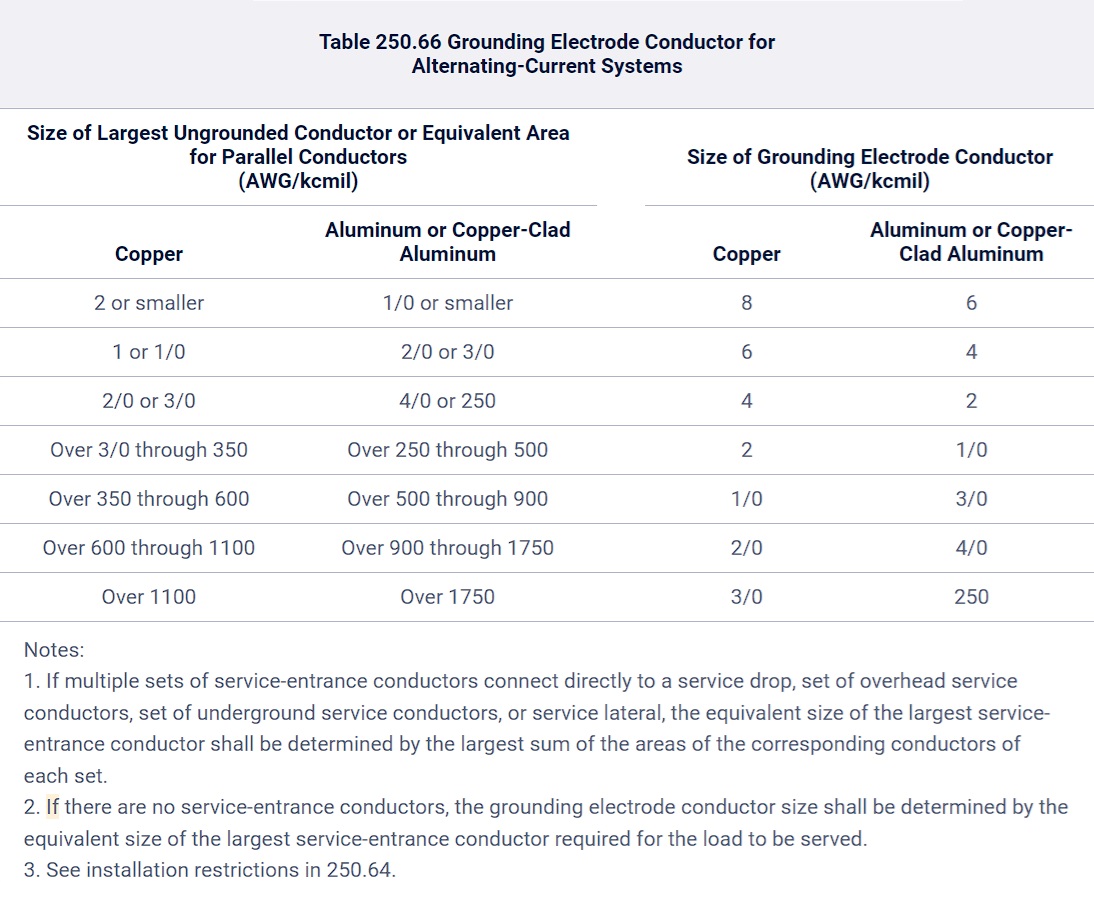
(A) Connections to a Rod, Pipe, or Plate Electrode(s).
If the grounding electrode conductor or bonding jumper connected to a single or multiple rod, pipe, or plate electrode(s), or any combination thereof, as described in 250.52(A)(5) or (A)(7), does not extend on to other types of electrodes that require a larger size conductor, the grounding electrode conductor shall not be required to be larger than 6 AWG copper wire or 4 AWG aluminum or copper-clad aluminum wire.
(B) Connections to Concrete-Encased Electrodes.
If the grounding electrode conductor or bonding jumper connected to a single or multiple concrete-encased electrode(s), as described in 250.52(A)(3), does not extend on to other types of electrodes that require a larger size of conductor, the grounding electrode conductor shall not be required to be larger than 4 AWG copper wire.
(C) Connections to Ground Rings.
If the grounding electrode conductor or bonding jumper connected to a ground ring, as described in 250.52(A)(4), does not extend on to other types of electrodes that require a larger size of conductor, the grounding electrode conductor shall not be required to be larger than the conductor used for the ground ring.
250.68 Grounding Electrode Conductor and Bonding Jumper Connection to Grounding Electrodes.
The connection of a grounding electrode conductor at the service, at each building or structure where supplied by a feeder(s) or branch circuit(s), or at a separately derived system and associated bonding jumper(s) shall be made as specified 250.68(A) through (C).
(A) Accessibility.
All mechanical elements used to terminate a grounding electrode conductor or bonding jumper to a grounding electrode shall be accessible.
Exception No. 1: An encased or buried connection to a concrete-encased, driven, or buried grounding electrode shall not be required to be accessible.
Exception No. 2: Exothermic or irreversible compression connections used at terminations, together with the mechanical means used to attach such terminations to fireproofed structural metal whether or not the mechanical means is reversible, shall not be required to be accessible.
(B) Effective Grounding Path.
The connection of a grounding electrode conductor or bonding jumper to a grounding electrode shall be made in a manner that will ensure an effective grounding path. Where necessary to ensure the grounding path for a metal piping system used as a grounding electrode, bonding shall be provided around insulated joints and around any equipment likely to be disconnected for repairs or replacement. Bonding jumpers shall be of sufficient length to permit removal of such equipment while retaining the integrity of the grounding path.
(C) Grounding Electrode Conductor Connections.
Grounding electrode conductors and bonding jumpers shall be permitted to be connected at the following locations and used to extend the connection to an electrode(s):
(1) Interior metal water piping that is electrically continuous with a metal underground water pipe electrode and is located not more than 1.52 m (5 ft) from the point of entrance to the building, as measured along the water piping, shall be permitted to extend the connection to an electrode(s). Interior metal water piping located more than 1.52 m (5 ft) from the point of entrance to the building, as measured along the water piping, shall not be used as a conductor to interconnect electrodes of the grounding electrode system.
Exception: In industrial, commercial, and institutional buildings or structures, if conditions of maintenance and supervision ensure that only qualified persons service the installation, interior metal water piping located more than 1.52 m (5 ft) from the point of entrance to the building, as measured along the water piping, shall be permitted as a bonding conductor to interconnect electrodes that are part of the grounding electrode system, or as a grounding electrode conductor, if the entire length, other than short sections passing perpendicularly through walls, floors, or ceilings, of the interior metal water pipe that is being used for the conductor is exposed.
(2) The metal structural frame of a building shall be permitted to be used as a conductor to interconnect electrodes that are part of the grounding electrode system, or as a grounding electrode conductor. Hold-down bolts securing the structural steel column that are connected to a concrete-encased electrode complying with 250.52(A)(3) and located in the support footing or foundation shall be permitted to connect the metal structural frame of a building or structure to the concrete-encased grounding electrode. The hold-down bolts shall be connected to the concrete-encased electrode by welding, exothermic welding, steel tie wires, or other approved means.
(3) A rebar-type concrete-encased electrode installed in accordance with 250.52(A)(3) with an additional rebar section extended from its location within the concrete foundation or footing to an accessible location that is not subject to corrosion shall be permitted for connection of grounding electrode conductors and bonding jumpers in accordance with the following:
a. The additional rebar section shall be continuous with the grounding electrode rebar or shall be connected to the grounding electrode rebar and connected together by steel tie wires, exothermic welding, welding, or other effective means.
b. The rebar extension shall not be exposed to contact with the earth without corrosion protection.
c. Rebar shall not be used as a conductor to interconnect the electrodes of grounding electrode systems.
250.70 Methods of Grounding and Bonding Conductor Connection to Electrodes.
(A) General.
The grounding or bonding conductor shall be connected to the grounding electrode by exothermic welding, listed lugs, listed pressure connectors, listed clamps, or other listed means. Connections depending on solder shall not be used. Ground clamps shall be listed for the materials of the grounding electrode and the grounding electrode conductor and, if used on pipe, rod, or other buried electrodes, shall also be listed for direct soil burial or concrete encasement. Not more than one conductor shall be connected to the grounding electrode by a single clamp or fitting unless the clamp or fitting is listed for multiple conductors.
(B) Indoor Communications Systems.
For indoor communications purposes only, a listed sheet metal strap-type ground clamp having a rigid metal base that seats on the electrode and having a strap of such material and dimensions that it is not likely to stretch during or after installation shall be permitted.
Informational Note: Listed ground clamps that are identified for direct burial are also suitable for concrete encasement.
Part IV. Enclosure, Raceway, and Service Cable Connections
250.80 Service Raceways and Enclosures.
Metal enclosures and raceways for service conductors and equipment shall be connected to the grounded conductor if the electrical system is grounded or to the grounding electrode conductor for electrical systems that are not grounded.
Exception: Metal components that are installed in a run of underground nonmetallic raceway(s) and are isolated from possible contact by a minimum cover of 450 mm (18 in.) to all parts of the metal components shall not be required to be connected to the grounded conductor, supply-side bonding jumper, or grounding electrode conductor.
250.84 Underground Service Cable or Raceway.
(A) Underground Service Cable.
The sheath or armor of a continuous underground metal-sheathed or armored service cable system that is connected to the grounded conductor on the supply side shall not be required to be connected to the grounded conductor at the building or structure. The sheath or armor shall be permitted to be insulated from the interior metal raceway or piping.
(B) Underground Service Raceway Containing Cable.
An underground metal service raceway that contains a metal-sheathed or armored cable connected to the grounded conductor shall not be required to be connected to the grounded conductor at the building or structure. The sheath or armor shall be permitted to be insulated from the interior metal raceway or piping.
250.86 Other Conductor Enclosures and Raceways.
Except as permitted by 250.112(I), metal enclosures and raceways for other than service conductors shall be connected to the equipment grounding conductor.
Exception No. 1: Metal enclosures and raceways for conductors added to existing installations of open wire, knob-and-tube wiring, and nonmetallic-sheathed cable shall not be required to be connected to the equipment grounding conductor if these enclosures or wiring methods comply with all the following:
(1) Do not provide an equipment ground
(2) Are in runs of less than 7.5 m (25 ft)
(3) Are free from probable contact with ground, grounded metal, metal lath, or other conductive material
(4) Are guarded against contact by persons
Exception No. 2: Short sections of metal enclosures or raceways used to provide support or protection of cable assemblies from physical damage shall not be required to be connected to the equipment grounding conductor.
Exception No. 3: Metal components shall not be required to be connected to the equipment grounding conductor or supply-side bonding jumper if either of the following conditions exist:
(1) The metal components are installed in a run of nonmetallic raceway(s) and isolated from possible contact by a minimum cover of 450 mm (18 in.) to any part of the metal components.
(2) The metal components are part of an installation of nonmetallic raceway(s) and are isolated from possible contact to any part of the metal components by being encased in not less than 50 mm (2 in.) of concrete.
Part V. Bonding
250.90 General.
Bonding shall be provided if necessary to ensure electrical continuity and the capacity to conduct safely any fault current likely to be imposed.
250.92 Services.
(A) Bonding of Equipment for Services.
The normally non-current-carrying metal parts of equipment indicated in the following shall be bonded together:
(1) All raceways, cable trays, cablebus framework, auxiliary gutters, or service cable armor or sheath that enclose, contain, or support service conductors, except as permitted in 250.80
(2) All enclosures containing service conductors, including meter fittings, boxes, or the like, interposed in the service raceway or armor
(B) Method of Bonding at the Service.
Bonding jumpers meeting the requirements of this article shall be used around impaired connections, such as reducing washers or oversized, concentric, or eccentric knockouts. Standard locknuts or bushings shall not be the only means for the bonding required by this section but shall be permitted to be installed to make a mechanical connection of the raceway(s).
Electrical continuity at service equipment, service raceways, and service conductor enclosures shall be ensured by one or more of the following methods:
(1) Bonding equipment to the grounded service conductor by an applicable method in 250.8(A)
(2) Connections made up wrenchtight using threaded couplings, threaded entries, or listed threaded hubs on enclosures
(3) Threadless couplings and connectors if made up tight for metal raceways and metal-clad cables
(4) Other listed devices, such as bonding-type locknuts, bushings, or bushings with bonding jumpers
250.94 Bonding for Communications Systems.
Communications system bonding conductor terminations shall be connected in accordance with 250.94(A) or (B).
(A) The Intersystem Bonding Termination Device.
An intersystem bonding termination (IBT) for connecting intersystem bonding conductors shall be provided external to enclosures at the service equipment or metering equipment enclosure and at the disconnecting means for any buildings or structures that are supplied by a feeder or branch circuit. If an IBT is used, it shall comply with the following:
(1) Be accessible for connection and inspection
(2) Consist of a set of terminals with the capacity for connection of not less than three intersystem bonding conductors
(3) Not interfere with opening the enclosure for a service, building or structure disconnecting means, or metering equipment
(4) Be securely mounted as follows:
a. At the service equipment, to a metal enclosure for the service equipment, to a metal meter enclosure, or to an exposed nonflexible metal service raceway, or be connected to the metal enclosure for the grounding electrode conductor with a minimum 6 AWG copper conductor
b. At the disconnecting means for a building or structure that is supplied by a feeder or branch circuit, be electrically connected to the metal enclosure for the building or structure disconnecting means, or be connected to the metal enclosure for the grounding electrode conductor with a minimum 6 AWG copper conductor
(5) Be listed as grounding and bonding equipment
Exception: In existing buildings or structures, if any of the intersystem bonding and grounding electrode conductors required by 770.100(B)(2), 800.100(B)(2), 810.21(F)(2), and 820.100 exist, installation of an IBT shall not be required. An accessible means external to enclosures for connecting intersystem bonding and grounding electrode conductors shall be permitted at the service equipment and at the disconnecting means for any buildings or structures that are supplied by a feeder or branch circuit by at least one of the following means:
(1) Exposed nonflexible metal raceways
(2) An exposed grounding electrode conductor
(3) Approved means for the external connection of a copper or other corrosion-resistant bonding or grounding electrode conductor to the grounded raceway or equipment
Informational Note: See 770.100, 800.100, 810.21, and 820.100 for intersystem bonding and grounding requirements for conductive optical fiber cables, communications circuits, radio and television equipment, CATV circuits, and network-powered broadband communications systems, respectively.
(B) Other Means.
Connections to an aluminum or copper busbar not less than 6 mm thick × 50 mm wide (1⁄4 in. thick × 2 in. wide) and of a length to accommodate at least three terminations for communication systems in addition to other connections. The busbar shall be securely fastened and shall be installed in an accessible location. Connections shall be made by a listed connector. If aluminum busbars are used, the installation shall also comply with 250.64(A). The busbar shall be connected to the grounding electrode system by a conductor that is the larger of the following:
(1) The largest grounding electrode conductor that is connected to the busbar
(2) As required or permitted in 250.94(A)
Exception to (A) and (B): Means for connecting intersystem bonding conductors are not required if communications systems are not likely to be used in or on the building or structure.
Informational Note: The use of an IBT can reduce electrical noise on communication systems.
250.96 Bonding Other Enclosures.
(A) General.
Metal raceways, cable trays, cable armor, cable sheath, enclosures, frames, fittings, and other metal non-current-carrying parts that are to serve as equipment grounding conductors, with or without the use of wire-type supplementary equipment grounding conductors, shall be bonded if necessary to ensure electrical continuity and the capacity to conduct fault current likely to be imposed on them. Any nonconductive paint, enamel, or similar coating shall be removed at threads, contact points, and contact surfaces or shall be connected by means of fittings designed so as to make such removal unnecessary.
(B) Isolated Grounding Circuits.
If installed for the reduction of electromagnetic interference on the grounding circuit, an equipment enclosure supplied by a branch circuit shall be permitted to be isolated from a raceway containing circuits supplying only that equipment by one or more listed nonmetallic raceway fittings located at the point of attachment of the raceway to the equipment enclosure. The metal raceway shall comply with this article and shall be supplemented by an internal insulated equipment grounding conductor installed in accordance with 250.146(D) to ground the equipment enclosure.
Informational Note: Use of an isolated equipment grounding conductor does not relieve the requirement for grounding the raceway system.
c
250.97 Bonding for Over 250 Volts to Ground.
For circuits of over 250 volts to ground, the electrical continuity of metal raceways and cables with metal sheaths that contain any conductor other than service conductors shall be ensured by one or more of the methods specified for services in 250.92(B), except for (B)(1).
Exception: If oversized, concentric, or eccentric knockouts are not encountered, or if a box or enclosure with concentric or eccentric knockouts is listed to provide a reliable bonding connection, the following methods shall be permitted:
(1) Threadless couplings and connectors for cables with metal sheaths
(2) Two locknuts, on rigid metal conduit or intermediate metal conduit, one inside and one outside of boxes and cabinets
(3) Fittings with shoulders that seat tightly against the box or cabinet, such as electrical metallic tubing connectors, flexible metal conduit connectors, and cable connectors, with one locknut on the inside of boxes and cabinets
(4) Listed fittings
250.98 Bonding Loosely Jointed Metal Raceways.
Expansion, expansion-deflection, or deflection fittings and telescoping sections of metal raceways shall be made electrically continuous by equipment bonding jumpers or other means.
250.100 Bonding in Hazardous (Classified) Locations.
Regardless of the voltage of the electrical system, the electrical continuity of normally non-current-carrying metal parts of electrical equipment, raceways, metal-clad cable, and metal enclosures containing electrical equipment in any hazardous (classified) location, as defined in 500.5, 505.5, and 506.5, shall be ensured by any of the bonding methods specified in 250.92(B)(2) through (B)(4). One or more of these bonding methods shall be used whether or not equipment grounding conductors of the wire type are installed in the raceway or in a multiconductor cable assembly.
Informational Note: See 501.30, 502.30, 503.30, 505.30, or 506.30 for specific bonding requirements.
250.102 Grounded Conductor, Bonding Conductors, and Jumpers.
(A) Material.
Bonding jumpers shall be of copper, aluminum, copper-clad aluminum, or other corrosion-resistant material. A bonding jumper shall be a wire, bus, screw, or similar suitable conductor.
(B) Attachment.
Bonding jumpers shall be attached in the manner specified in 250.8 for circuits and equipment and in 250.70 for grounding electrodes.
(C) Size — Supply-Side Bonding Jumper.
(1) Size for Supply Conductors in a Single Raceway or Cable.
The supply-side bonding jumper shall not be smaller than specified in Table 250.102(C)(1).
(2) Size for Parallel Conductor Installations in Two or More Raceways or Cables.
If the ungrounded supply conductors are connected in parallel in two or more raceways or cables, the supply-side bonding jumper shall be sized in accordance with either of the following:
(1) An individual bonding jumper for each raceway or cable shall be selected from Table 250.102(C)(1) based on the size of the largest ungrounded supply conductor in each raceway or cable.
(2) A single bonding jumper installed for bonding two or more raceways or cables shall be sized in accordance with Table 250.102(C)(1) based on the sum of the circular mil areas of the largest ungrounded conductors from each set connected in parallel in each raceway or cable. The size of the grounded conductor(s) in each raceway or cable shall be based on the largest ungrounded conductor in each raceway or cable, or the sum of the circular mil areas of the largest ungrounded conductors from each set connected in parallel in each raceway or cable.
Informational Note No. 1: The term supply conductors includes ungrounded conductors that do not have overcurrent protection on their supply side and terminate at service equipment or the first disconnecting means of a separately derived system.
Informational Note No. 2: See Chapter 9, Table 8, for the circular mil area of conductors 18 AWG through 4/0 AWG.
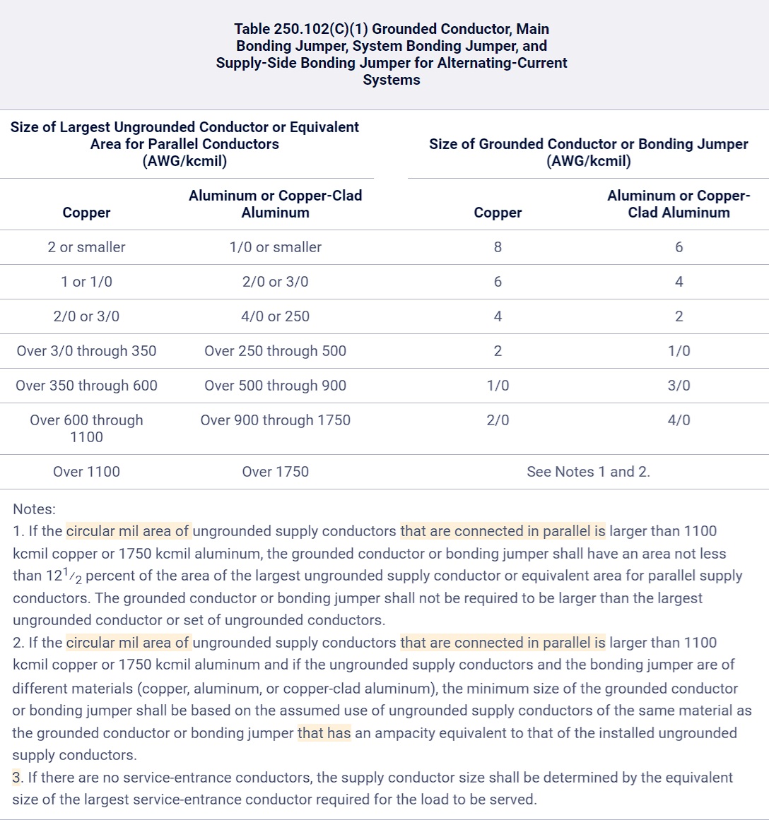
(D) Size — Equipment Bonding Jumper on Load Side of an Overcurrent Device.
The equipment bonding jumper on the load side of an overcurrent device(s) shall be sized in accordance with 250.122.
A single common continuous equipment bonding jumper shall be permitted to connect two or more raceways or cables if the bonding jumper is sized in accordance with 250.122 for the largest overcurrent device supplying circuits therein.
(E) Installation.
Bonding jumpers or conductors and equipment bonding jumpers shall be permitted to be installed inside or outside of a raceway or an enclosure.
(1) Inside a Raceway or an Enclosure.
If installed inside a raceway, equipment bonding jumpers and bonding jumpers or conductors shall comply with the requirements of 250.119 and 250.148.
(2) Outside a Raceway or an Enclosure.
If installed on the outside, the length of the bonding jumper or conductor or equipment bonding jumper shall not exceed 1.8 m (6 ft) and shall be routed with the raceway or enclosure.
Exception: An equipment bonding jumper or supply-side bonding jumper longer than 1.8 m (6 ft) shall be permitted at outside pole locations for the purpose of bonding or grounding isolated sections of metal raceways or elbows installed in exposed risers of metal conduit or other metal raceway, and for bonding grounding electrodes, and shall not be required to be routed with a raceway or enclosure.
(3) Protection.
Bonding jumpers or conductors and equipment bonding jumpers shall be installed in accordance with 250.64(A) and (B).
50.106 Lightning Protection Systems.
The lightning protection system ground terminals shall be bonded to the building or structure grounding electrode system.
Informational Note No. 1: See 250.60 for use of strike termination devices.
Informational Note No. 2: See NFPA 780, Standard for the Installation of Lightning Protection Systems, which contains detailed information on grounding, bonding, and sideflash distance from lightning protection systems.
Part VI. Equipment Grounding and Equipment Grounding Conductors
250.109 Metal Enclosures.
Metal enclosures shall be permitted to be used to connect bonding jumpers or equipment grounding conductors, or both, together to become a part of an effective ground-fault current path. If installed, metal covers, plaster rings, extension rings, and metal fittings shall be attached to these metal enclosures to ensure an effective ground-fault current path or shall be connected with bonding jumpers or equipment grounding conductors, or both.
Informational Note: See 250.97 for bonding requirements for over 250 volts to ground.
250.110 Equipment Fastened in Place (Fixed) or Connected by Permanent Wiring Methods.
Exposed, normally non-current-carrying metal parts of fixed equipment supplied by or enclosing conductors or components that are likely to become energized shall be connected to an equipment grounding conductor under any of the following conditions:
(1) If within 2.5 m (8 ft) vertically or 1.5 m (5 ft) horizontally of ground or grounded metal objects and subject to contact by persons
(2) If located in a wet or damp location and not isolated
(3) If in electrical contact with metal
(4) If in a hazardous (classified) location
(5) If supplied by a wiring method that provides an equipment grounding conductor, except as permitted by 250.86, Exception No. 2, for short sections of metal enclosures
(6) If equipment operates with any terminal at over 150 volts to ground
Exception No. 1: If exempted by special permission, the metal frame of electrically heated appliances that have the frame permanently and effectively insulated from ground shall not be required to be grounded.
Exception No. 2: Distribution apparatus, such as transformer and capacitor cases, mounted on wooden poles at a height exceeding 2.5 m (8 ft) above ground or grade level shall not be required to be grounded.
Exception No. 3: Listed equipment protected by a system of double insulation, or its equivalent, shall not be required to be connected to the equipment grounding conductor. If such a system is employed, the equipment shall be distinctively marked.
250.112 Specific Equipment Fastened in Place (Fixed) or Connected by Permanent Wiring Methods.
Except as permitted in 250.112(F) and (I), exposed, normally non-current-carrying metal parts of equipment described in 250.112(A) through (K), and normally non-current-carrying metal parts of equipment and enclosures described in 250.112(L) and (M), shall be connected to an equipment grounding conductor, regardless of voltage.
(A) Switchgear and Switchboard Frames and Structures.
Switchgear or switchboard frames and structures supporting switching equipment, except frames of 2-wire dc switchgear or switchboards if effectively insulated from ground.
(B) Pipe Organs.
Generator and motor frames in an electrically operated pipe organ, unless effectively insulated from ground and the motor driving it.
(C) Motor Frames.
Motor frames, as provided by 430.242.
(D) Enclosures for Motor Controllers.
Enclosures for motor controllers unless attached to ungrounded portable equipment.
(E) Elevators and Cranes.
Electrical equipment for elevators and cranes.
(F) Garages, Theaters, and Motion Picture Studios.
Electrical equipment in commercial garages, theaters, and motion picture studios, except pendant lampholders supplied by circuits not over 150 volts to ground.
(G) Electric Signs.
Electric signs, outline lighting, and associated equipment as provided in 600.7.
(H) Motion Picture Projection Equipment.
Motion picture projection equipment.
(I) Remote-Control, Signaling, and Fire Alarm Circuits.
Equipment supplied by Class 1 circuits shall be grounded unless operating at less than 50 volts. Equipment supplied by Class 1 power-limited circuits, by Class 2 and Class 3 remote-control and signaling circuits, and by fire alarm circuits shall be grounded if system grounding is required by Part II or Part VIII of this article.
(J) Luminaires.
Luminaires as provided in Part V of Article 410.
(K) Skid-Mounted Equipment.
Permanently mounted electrical equipment and skids shall be connected to the equipment grounding conductor. Wire-type equipment grounding conductors shall be sized as required by 250.122.
(L) Motor-Operated Water Pumps.
Motor-operated water pumps, including the submersible type.
(M) Metal Well Casings.
If a submersible pump is used in a metal well casing, the well casing shall be connected to the pump circuit equipment grounding conductor.
250.114 Equipment Connected by Cord and Plug.
Exposed, normally non-current-carrying metal parts of cord-and-plug-connected equipment shall be connected to the equipment grounding conductor under any of the following conditions:
Exception: Listed tools, listed appliances, and listed equipment covered in 250.114, list items 2 through 4, shall not be required to be connected to an equipment grounding conductor if protected by a system of double insulation or its equivalent. Double-insulated equipment shall be distinctively marked.
(1) In hazardous (classified) locations
(2) If operated at over 150 volts to ground
Exception No. 1 to (2): Motors, if guarded, shall not be required to be connected to an equipment grounding conductor.
Exception No. 2 to (2): Metal frames of electrically heated appliances, exempted by special permission, shall not be required to be connected to an equipment grounding conductor, in which case the frames shall be permanently and effectively insulated from ground.
(3) In residential occupancies:
a. Refrigerators, freezers, icemakers, and air conditioners
b. Clothes-washing, clothes-drying, and dish-washing machines; ranges; kitchen waste disposers; information technology equipment; sump pumps; and electrical aquarium equipment
c. Hand-held motor-operated tools, stationary and fixed motor-operated tools, and light industrial motor-operated tools
d. Motor-operated appliances of the following types: hedge clippers, lawn mowers, snow blowers, and wet scrubbers
e. Portable handlamps
(4) In other than residential occupancies:
a. Refrigerators, freezers, icemakers, and air conditioners
b. Clothes-washing, clothes-drying, and dish-washing machines; information technology equipment; sump pumps; and electrical aquarium equipment
c. Hand-held motor-operated tools, stationary and fixed motor-operated tools, and light industrial motor-operated tools
d. Motor-operated appliances of the following types: hedge clippers, lawn mowers, snow blowers, and wet scrubbers
e. Portable handlamps
f. Cord-and-plug-connected appliances used in damp or wet locations or by persons standing on the ground, standing on metal floors, or working inside of metal tanks or boilers
250.116 Nonelectrical Equipment.
The metal parts of the following nonelectrical equipment described in this section shall be connected to the equipment grounding conductor:
(1) Frames and tracks of electrically operated cranes and hoists
(2) Frames of nonelectrically driven elevator cars to which electrical conductors are attached
(3) Hand-operated metal shifting ropes or cables of electric elevators
Informational Note: If extensive metal in or on buildings or structures may become energized and is subject to personal contact, adequate bonding and grounding will provide additional safety.
250.118 Types of Equipment Grounding Conductors.
(A) Permitted.
Each equipment grounding conductor run with or enclosing the circuit conductors shall be one or more or a combination of the following:
(1) A copper, aluminum, or copper-clad aluminum conductor. This conductor shall be solid or stranded; insulated, covered, or bare; and in the form of a wire or a busbar of any shape.
(2) Rigid metal conduit.
(3) Intermediate metal conduit.
(4) Electrical metallic tubing.
(5) Listed flexible metal conduit meeting all the following conditions:
a. The conduit is terminated in listed fittings.
b. The circuit conductors contained in the conduit are protected by overcurrent devices rated at 20 amperes or less.
c. The size of the conduit does not exceed metric designator 35 (trade size 11⁄4).
d. The combined length of flexible metal conduit, flexible metallic tubing, and liquidtight flexible metal conduit in the same effective ground-fault current path does not exceed 1.8 m (6 ft).
e. If flexibility is necessary to minimize the transmission of vibration from equipment or to provide flexibility for equipment that requires movement after installation, a wire-type equipment grounding conductor or a bonding jumper in accordance with 250.102(E)(2) shall be installed.
f. If flexible metal conduit is constructed of stainless steel, a wire-type equipment grounding conductor or bonding jumper in accordance with 250.102(E)(2) shall be installed.
(6) Listed liquidtight flexible metal conduit meeting all the following conditions:
a. The conduit is terminated in listed fittings.
b. For metric designators 12 through 16 (trade sizes 3⁄8 through 1⁄2), the circuit conductors contained in the conduit are protected by overcurrent devices rated at 20 amperes or less.
c. For metric designators 21 through 35 (trade sizes 3⁄4 through 11⁄4), the circuit conductors contained in the conduit are protected by overcurrent devices rated not more than 60 amperes and there is no flexible metal conduit, flexible metallic tubing, or liquidtight flexible metal conduit in metric designators 12 through 16 (trade sizes 3⁄8 through 1⁄2) in the effective ground-fault current path.
d. The combined length of flexible metal conduit, flexible metallic tubing, and liquidtight flexible metal conduit in the same effective ground-fault current path does not exceed 1.8 m (6 ft).
e. If flexibility is necessary to minimize the transmission of vibration from equipment or to provide flexibility for equipment that requires movement after installation, a wire-type equipment grounding conductor or a bonding jumper in accordance with 250.102(E)(2) shall be installed.
f. If liquidtight flexible metal conduit contains a stainless steel core, a wire-type equipment grounding conductor or a bonding jumper in accordance with 250.102(E)(2) shall be installed.
(7) Flexible metallic tubing if the tubing is terminated in listed fittings and meeting the following conditions:
a. The circuit conductors contained in the tubing are protected by overcurrent devices rated at 20 amperes or less.
b. The combined length of flexible metal conduit, flexible metallic tubing, and liquidtight flexible metal conduit in the same effective ground-fault current path does not exceed 1.8 m (6 ft).
(8) Armor of Type AC cable as provided in 320.108.
(9) The copper sheath of mineral-insulated, metal-sheathed cable Type MI.
(10) Type MC cable that provides an effective ground-fault current path in accordance with one or more of the following:
a. It contains an insulated or uninsulated equipment grounding conductor in compliance with 250.118(1).
b. The combined metallic sheath and uninsulated equipment grounding/bonding conductor of interlocked metal tape–type MC cable that is listed and identified as an equipment grounding conductor
c. The metallic sheath or the combined metallic sheath and equipment grounding conductors of the smooth or corrugated tube-type MC cable that is listed and identified as an equipment grounding conductor
(11) Cable trays as permitted in 392.10 and 392.60.
(12) Cablebus framework as permitted in 370.60(1).
(13) Other listed electrically continuous metal raceways and listed auxiliary gutters.
(14) Surface metal raceways listed for grounding.
Informational Note: See Article 100 for a definition of effective ground-fault current path.
(B) Not Permitted.
The following shall not be used as equipment grounding conductors.
(1) Grounding electrode conductors
Exception: A wire-type equipment grounding conductor installed in compliance with 250.6(A) and the applicable requirements for both the equipment grounding conductor and the grounding electrode conductor in Parts II, III, and VI of this article shall be permitted to serve as both an equipment grounding conductor and a grounding electrode conductor.
(2) Structural metal frame of a building or structure
250.120 Equipment Grounding Conductor Installation.
An equipment grounding conductor shall be installed in accordance with 250.120(A), (B), and (C).
(A) Raceway, Cable Trays, Cable Armor, Cablebus, or Cable Sheaths.
If it consists of a raceway, cable tray, cable armor, cablebus framework, or cable sheath or if it is a wire within a raceway or cable, it shall be installed in accordance with the applicable provisions in this Code using fittings for joints and terminations approved for use with the type of raceway or cable used. All connections, joints, and fittings shall be made tight using suitable tools.
Informational Note: See the UL Guide Information for Electrical Circuit Integrity Systems (FHIT) for equipment grounding conductors installed in a raceway that are part of a listed electrical circuit protective system or a listed fire-resistive cable system.
(B) Aluminum and Copper-Clad Aluminum Conductors.
Equipment grounding conductors of bare, covered, or insulated aluminum or copper-clad aluminum shall comply with the following:
(1) Unless part of an applicable cable wiring method, bare or covered conductors shall not be installed if subject to corrosive conditions or be installed in direct contact with concrete, masonry, or the earth.
(2) Terminations made within outdoor enclosures that are listed and identified for the environment shall be permitted within 450 mm (18 in.) of the bottom of the enclosure.
(3) Aluminum or copper-clad aluminum conductors external to buildings or enclosures shall not be terminated within 450 mm (18 in.) of the earth, unless terminated within a listed wire connector system.
(C) Equipment Grounding Conductors Smaller Than 6 AWG.
If not routed with circuit conductors as permitted in 250.130(C) and 250.134, Exception No. 2, equipment grounding conductors smaller than 6 AWG shall be protected from physical damage by an identified raceway or cable armor unless installed within hollow spaces of the framing members of buildings or structures and if not subject to physical damage.
250.122 Size of Equipment Grounding Conductors.
(A) General.
Copper, aluminum, or copper-clad aluminum equipment grounding conductors of the wire type shall not be smaller than shown in Table 250.122. The equipment grounding conductor shall not be required to be larger than the circuit conductors supplying the equipment. If a cable tray, a raceway, or a cable armor or sheath is used as the equipment grounding conductor, as provided in 250.118 and 250.134(1), it shall comply with 250.4(A)(5) or (B)(4).
Equipment grounding conductors shall be permitted to be sectioned within a multiconductor cable, provided the combined circular mil area complies with.Table 250.122.
(B) Increased in Size.
If ungrounded conductors are increased in size for any reason other than as required in 310.15(B) or 310.15(C), wire-type equipment grounding conductors, if installed, shall be increased in size proportionately to the increase in circular mil area of the ungrounded conductors.
Exception: Equipment grounding conductors shall be permitted to be sized by a qualified person to provide an effective ground fault current path in accordance with 250.4(A)(5) or (B)(4)
(C) Multiple Circuits.
A single equipment grounding conductor shall be permitted to be installed for multiple circuits that are installed in the same raceway, cable, trench, or cable tray. It shall be sized from Table 250.122 for the largest overcurrent device protecting circuit conductors in the raceway, cable, trench, or cable tray. Equipment grounding conductors installed in cable trays shall meet the minimum requirements of 392.10(B)(1)(c).
(D) Motor Circuits.
Equipment grounding conductors for motor circuits shall be sized in accordance with 250.122(D)(1) or (D)(2).
(1) General. The equipment grounding conductor size shall not be smaller than determined by 250.122(A) based on the rating of the branch-circuit short-circuit and ground-fault protective device.
(2) Instantaneous-Trip Circuit Breaker and Motor Short-Circuit Protector.
If the overcurrent device is an instantaneous-trip circuit breaker or a motor short-circuit protector, the equipment grounding conductor shall be sized not smaller than that given by 250.122(A) using the maximum permitted rating of a dual element time-delay fuse selected for branch-circuit short-circuit and ground-fault protection in accordance with 430.52(C)(1)(a).
(E) Flexible Cord and Fixture Wire.
The equipment grounding conductor in a flexible cord with the largest circuit conductor 10 AWG or smaller, and the equipment grounding conductor used with fixture wires of any size in accordance with 240.5, shall not be smaller than 18 AWG copper and shall not be smaller than the circuit conductors. The equipment grounding conductor in a flexible cord with a circuit conductor larger than 10 AWG shall be sized in accordance with Table 250.122.
(F) Conductors in Parallel.
For circuits of parallel conductors as permitted in 310.10(G), the equipment grounding conductor shall be installed in accordance with 250.122(F)(1) or (F)(2).
(1) Conductor Installations in Raceways, Auxiliary Gutters, or Cable Trays.
(a) Single Raceway or Cable Tray, Auxiliary Gutter, or Cable Tray. If circuit conductors are connected in parallel in the same raceway, auxiliary gutter, or cable tray, a single wire-type conductor shall be permitted as the equipment grounding conductor. The wire-type equipment grounding conductor shall be sized in accordance with 250.122 based on the overcurrent protective device for the feeder or branch circuit.
(b) Multiple Raceways. If conductors are installed in multiple raceways and are connected in parallel, a wire-type equipment grounding conductor, if used, shall be installed in each raceway and shall be connected in parallel. The equipment grounding conductor installed in each raceway shall be sized in accordance with 250.122 based on the rating of the overcurrent protective device for the feeder or branch circuit.
(c) Wire-Type Equipment Grounding Conductors in Cable Trays. Wire-type equipment grounding conductors installed in cable trays shall meet the minimum requirements of 392.10(B)(1)(c).
(d) Metal Raceways, Auxiliary Gutters, or Cable Trays. Metal raceways or auxiliary gutters in accordance with 250.118 or cable trays complying with 392.60(B) shall be permitted as the equipment grounding conductor.
(2) Multiconductor Cables.
(a) Except as provided in 250.122(F)(2)(c) for raceway or cable tray installations, the equipment grounding conductor in each multiconductor cable shall be sized in accordance with 250.122 based on the overcurrent protective device for the feeder or branch circuit.
(b) If circuit conductors of multiconductor cables are connected in parallel, the equipment grounding conductor(s) in each cable shall be connected in parallel.
(c) If multiconductor cables are paralleled in the same raceway, auxiliary gutter, or cable tray, a single equipment grounding conductor that is sized in accordance with 250.122 shall be permitted in combination with the equipment grounding conductors provided within the multiconductor cables and shall all be connected together.
(d) Equipment grounding conductors installed in cable trays shall meet the minimum requirements of 392.10(B)(1)(c). Cable trays complying with 392.60(B), metal raceways in accordance with 250.118, or auxiliary gutters shall be permitted as the equipment grounding conductor.
(G) Feeder Taps.
Equipment grounding conductors installed with feeder taps shall not be smaller than shown in Table 250.122 based on the rating of the overcurrent device ahead of the feeder on the supply side ahead of the tap but shall not be required to be larger than the tap conductors.

250.124 Equipment Grounding Conductor Continuity.
(A) Separable Connections.
Separable connections such as those provided in drawout equipment or attachment plugs and mating connectors and receptacles shall provide for first-make, last-break of the equipment grounding conductor. First-make, last-break shall not be required if interlocked equipment, plugs, receptacles, and connectors preclude energization without grounding continuity.
(B) Switches.
No automatic cutout or switch shall be placed in the equipment grounding conductor of a premises wiring system unless the opening of the cutout or switch disconnects all sources of energy.
250.126 Identification of Wiring Device Terminals.
The terminal for the connection of the equipment grounding conductor shall be identified by one of the following:
(1) A green, not readily removable terminal screw with a hexagonal head.
(2) A green, hexagonal, not readily removable terminal nut.
(3) A green pressure wire connector. If the terminal for the equipment grounding conductor is not visible, the conductor entrance hole shall be marked with the word green or ground, the letters G or GR, a grounding symbol, or otherwise identified by a distinctive green color. If the terminal for the equipment grounding conductor is readily removable, the area adjacent to the terminal shall be similarly marked.
Informational Note: See Informational Note Figure 250.126.
Informational Note Figure 250.126 One Example of a Symbol Used to Identify the Grounding Termination Point for an Equipment Grounding Conductor.
Part VII. Methods of Equipment Grounding Conductor Connections
250.130 Equipment Grounding Conductor Connections.
Equipment grounding conductor connections at the source of separately derived systems shall be made in accordance with 250.30(A)(1). Equipment grounding conductor connections at service equipment shall be made as indicated in 250.130(A) or (B). For replacement of non-grounding-type receptacles with grounding-type receptacles, or snap switches without an equipment grounding terminal with snap switches with an equipment grounding terminal, and for branch-circuit extensions only in existing installations that do not have an equipment grounding conductor in the branch circuit, connections shall be permitted as indicated in 250.130(C).
(A) For Grounded Systems.
The connection shall be made by bonding the equipment grounding conductor to the grounded service conductor and the grounding electrode conductor.
(B) For Ungrounded Systems.
The connection shall be made by bonding the equipment grounding conductor to the grounding electrode conductor.
(C) Replacement of Nongrounding Receptacle or Snap Switch and Branch Circuit Extensions.
The equipment grounding conductor that is connected to a grounding-type receptacle, a snap switch with an equipment grounding terminal, or a branch-circuit extension shall be permitted to be connected to any of the following:
(1) Any accessible point on the grounding electrode system as described in 250.50
(2) Any accessible point on the grounding electrode conductor
(3) The equipment grounding terminal bar within the enclosure where the branch circuit for the receptacle or branch circuit originates
(4) An equipment grounding conductor that is part of another branch circuit that originates from the enclosure where the branch circuit for the receptacle, snap switch, or branch circuit originates
(5) For grounded systems, the grounded service conductor within the service equipment enclosure
(6) For ungrounded systems, the grounding terminal bar within the service equipment enclosure
Informational Note No. 1: See 406.4(D) for the use of a ground-fault circuit-interrupting type of receptacle.
Informational Note No. 2: See 404.9(B) for requirements regarding grounding of snap switches.
250.132 Short Sections of Raceway or Cable Armor.
Isolated sections of metal raceway or cable armor, if required to be connected to an equipment grounding conductor, shall be connected in accordance with 250.134.
250.134 Equipment Fastened in Place or Connected by Permanent Wiring Methods (Fixed).
Unless connected to the grounded circuit conductor as permitted by 250.32, 250.140, and 250.142, non-current-carrying metal parts of equipment, raceways, and other enclosures, if grounded, shall be connected to an equipment grounding conductor by one of the following methods:
(1) By connecting to any of the equipment grounding conductors permitted by 250.118(2) through (14)
(2) By connecting to an equipment grounding conductor of the wire type that is contained within the same raceway, contained within the same cable, or otherwise run with the circuit conductors
Exception No. 1: As provided in 250.130(C), the equipment grounding conductor shall be permitted to be run separately from the circuit conductors.
Exception No. 2: For dc circuits, the equipment grounding conductor shall be permitted to be run separately from the circuit conductors
Informational Note No. 1: See 250.102 and 250.168 for equipment bonding jumper requirements.
Informational Note No. 2: See 400.10 for use of flexible cords and flexible cables for fixed equipment.
250.136 Equipment Secured to a Metal Rack or Structure.
If a metal rack or structure is connected to an equipment grounding conductor in accordance with 250.134, it shall be permitted to serve as the equipment grounding conductor for electrical equipment secured to and in electrical contact with the metal rack or structure.
250.138 Cord-and-Plug-Connected Equipment.
Non–current-carrying metal parts of cord-and-plug-connected equipment, if required to be connected to an equipment grounding conductor, shall be connected by one of the methods in 250.138(A) or (B).
(A) By Means of an Equipment Grounding Conductor.
By means of an equipment grounding conductor run with the power supply conductors in a cable assembly or flexible cord properly terminated in a grounding-type attachment plug with one fixed grounding contact.
Exception: The grounding contacting pole of grounding-type plug-in ground-fault circuit interrupters shall be permitted to be of the movable, self-restoring type on circuits operating at not over 150 volts between any two conductors or over 150 volts between any conductor and ground.
(B) By Means of a Separate Flexible Wire or Strap.
By means of a separate flexible wire or strap, insulated or bare, connected to an equipment grounding conductor, and protected as well as practicable against physical damage, if part of equipment.
250.140 Frames of Ranges and Clothes Dryers.
Frames of electric ranges, wall-mounted ovens, counter-mounted cooking units, clothes dryers, and outlet or junction boxes that are part of the circuit shall be connected to the equipment grounding conductor in accordance with 250.140(A) or the grounded conductor in accordance with 250.140(B).
(A) Equipment Grounding Conductor Connections.
The circuit supplying the appliance shall include an equipment grounding conductor. The frame of the appliance shall be connected to the equipment grounding conductor in the manner specified by 250.134 or 250.138.
(B) Grounded Conductor Connections.
For existing branch-circuit installations only, if an equipment grounding conductor is not present in the outlet or junction box the frame of the appliance shall be permitted to be connected to the grounded conductor if all the conditions in the following list items (1), (2), and (3) are met and the grounded conductor complies with either list item (4) or (5):
(1) The supply circuit is 120/240-volt, single-phase, 3-wire; or 208Y/120-volt derived from a 3-phase, 4-wire, wye-connected system.
(2) The grounded conductor is not smaller than 10 AWG copper or 8 AWG aluminum or copper-clad aluminum.
(3) Grounding contacts of receptacles furnished as part of the equipment are bonded to the equipment.
(4) The grounded conductor is insulated, or the grounded conductor is uninsulated and part of a Type SE service-entrance cable and the branch circuit originates at the service equipment.
(5) The grounded conductor is part of a Type SE service-entrance cable that originates in equipment other than a service. The grounded conductor shall be insulated or field covered within the supply enclosure with listed insulating material, such as tape or sleeving to prevent contact of the uninsulated conductor with any normally non-current-carrying metal parts.
250.142 Use of Grounded Circuit Conductor for Grounding Equipment.
(A) Supply-Side Equipment.
A grounded circuit conductor shall be permitted to be connected to non-current-carrying metal parts of equipment, raceways, and other enclosures at any of the following locations:
(1) On the supply side or within the enclosure of the ac service disconnecting means
(2) On the supply side or within the enclosure of the main disconnecting means for separate buildings as provided in 250.32(B)(1) Exception No. 1
(3) On the supply side or within the enclosure of the main disconnecting means or overcurrent devices of a separately derived system where permitted by 250.30(A)(1)
B) Load-Side Equipment.
Except as permitted in 250.30(A)(1), 250.32(B)(1), Exception No. 1, and Part X of Article 250, a grounded circuit conductor shall not be connected to non–current-carrying metal parts of equipment on the load side of the service disconnecting means or on the load side of a separately derived system disconnecting means or the overcurrent devices for a separately derived system not having a main disconnecting means.
Exception No. 1: The frames of ranges, wall-mounted ovens, counter-mounted cooking units, and clothes dryers under the conditions permitted for existing installations by 250.140 shall be permitted to be connected to the grounded circuit conductor.
Exception No. 2: It shall be permissible to connect meter enclosures to the grounded circuit conductor on the load side of the service disconnect if all of the following conditions apply:
(1) Ground-fault protection of equipment is not installed.
(2) All meter enclosures are located immediately adjacent to the service disconnecting means.
(3) The size of the grounded circuit conductor is not smaller than the size specified in Table 250.122 for equipment grounding conductors.
Exception No. 3: Electrode-type boilers operating at over 1000 volts shall be grounded as required in 495.72(E)(1) and 495.74.
250.144 Multiple Circuit Connections.
If equipment is required to be grounded and is supplied by more than one circuit containing an equipment grounding conductor, a means to terminate each equipment grounding conductor meeting the requirements of 250.8 shall be provided as specified in 250.134 and 250.138.
250.146 Connecting Receptacle Grounding Terminal to an Equipment Grounding Conductor.
An equipment bonding jumper shall be used to connect the grounding terminal of a grounding-type receptacle to a metal box that is connected to an equipment grounding conductor, except as permitted in 250.146(A) through (D). The equipment bonding jumper shall be sized in accordance with Table 250.122.
(A) Surface-Mounted Box.
If a metal box is mounted on the surface, the direct metal-to-metal contact between the device yoke or strap to the box shall be permitted to provide the required effective ground-fault current path. At least one of the insulating washers shall be removed from receptacles that do not have a contact yoke or device to ensure direct metal-to-metal contact. Direct metal-to-metal contact for providing continuity applies to cover-mounted receptacles if the box and cover combination are listed as providing continuity between the box and the receptacle. A listed exposed work cover shall be permitted to be the grounding and bonding means under both of the following conditions:
(1) The device is attached to the cover with at least two fasteners that are permanent (such as a rivet) or have a thread-locking or screw- or nut-locking means.
(2) The cover mounting holes are located on a flat nonraised portion of the cover.
(B) Contact Devices or Yokes.
Contact devices or yokes designed and listed as self-grounding shall be permitted in conjunction with the supporting screws to establish equipment bonding between the device yoke and flush-type boxes.
(C) Floor Boxes.
Floor boxes designed for and listed as providing continuity between the box and the device shall be permitted.
(D) Isolated Ground Receptacles.
If installed for the reduction of electromagnetic interference on the equipment grounding conductor, a receptacle in which the grounding terminal is purposely insulated from the receptacle mounting means shall be permitted. The receptacle grounding terminal shall be connected to an insulated equipment grounding conductor run with the circuit conductors. This equipment grounding conductor shall be permitted to pass through one or more panelboards without a connection to the panelboard grounding terminal bar as permitted in 408.40, Exception, so as to terminate within the same building or structure directly at an equipment grounding conductor terminal of the applicable derived system or service. If installed in accordance with this section, this equipment grounding conductor shall also be permitted to pass through boxes, wireways, or other enclosures without being connected to such enclosures.
Informational Note: Use of an isolated equipment grounding conductor does not relieve the requirement for connecting the raceway system and outlet box to an equipment grounding conductor.
250.148 Continuity of Equipment Grounding Conductors and Attachment in Boxes.
If circuit conductors are spliced within a box or terminated on equipment within or supported by a box, the installation shall comply with 250.148(A) through (D).
Exception: The equipment grounding conductor permitted in 250.146(D) shall not be required to be connected to the other equipment grounding conductors or to the box.
(A) Connections and Splices.
All equipment grounding conductors that are spliced or terminated within the box shall be connected together. Connections and splices shall be made in accordance with 110.14(B) and 250.8 except that insulation shall not be required.
(B) Equipment Grounding Conductor Continuity.
The arrangement of grounding connections shall be such that the disconnection or the removal of a luminaire, receptacle, or other device fed from the box does not interrupt the electrical continuity of the equipment grounding conductor(s) providing an effective ground-fault current path.
(C) Metal Boxes.
A connection used for no other purpose shall be made between the metal box and the equipment grounding conductor(s). The equipment bonding jumper or equipment grounding conductor shall be sized from Table 250.122 based on the largest overcurrent device protecting circuit conductors in the box.
(D) Nonmetallic Boxes.
One or more equipment grounding conductors brought into a nonmetallic outlet box shall be arranged to provide a connection to any fitting or device in that box requiring connection to an equipment grounding conductor.
Part VIII. Direct-Current Systems
250.160 General.
Direct-current systems shall comply with Part VIII and other sections of Article 250 not specifically intended for ac systems
250.162 Direct-Current Circuits and Systems to Be Grounded.
Direct-current circuits and systems shall be grounded as provided for in 250.162(A) and (B).
(A) Two-Wire, Direct-Current Systems.
A 2-wire, dc system supplying premises wiring and operating at greater than 60 volts but not greater than 300 volts shall be grounded.
Exception No. 1: A system equipped with a ground detector and supplying only industrial equipment in limited areas shall not be required to be grounded if installed immediately adjacent to, or integral with, the source of supply.
Exception No. 2: A rectifier-derived dc system supplied from an ac system complying with 250.20 shall not be required to be grounded.
Exception No. 3: Direct-current fire alarm circuits having a maximum current of 0.030 ampere as specified in Article 760, Part III, shall not be required to be grounded.
(B) Three-Wire, Direct-Current Systems.
The neutral conductor of all 3-wire, dc systems supplying premises wiring shall be grounded.
250.164 Point of Connection for Direct-Current Systems.
(A) Off-Premises Source.
Direct-current systems to be grounded and supplied from an off-premises source shall have the grounding connection made at one or more supply stations. A grounding connection shall not be made at individual services or at any point on the premises wiring.
(B) On-Premises Source.
If the dc system source is located on the premises, a grounding connection shall be made at one of the following:
(1) The source
(2) The first system disconnection means or overcurrent device
(3) By other means that accomplish system protection and that use equipment listed and identified for the use
250.166 Size of the Direct-Current Grounding Electrode Conductor.
The size of the grounding electrode conductor for a dc system shall be as specified in 250.166(A) and (B), except as permitted by 250.166(C) through (E). The grounding electrode conductor for a dc system shall meet the sizing requirements in this section but shall not be required to be larger than 3/0 copper or 250 kcmil aluminum or copper-clad aluminum.
(A) Not Smaller Than the Neutral Conductor.
If the dc system consists of a 3-wire balancer set or a balancer winding with overcurrent protection as provided in 445.12(D), the grounding electrode conductor shall not be smaller than the neutral conductor and not smaller than 8 AWG copper or 6 AWG aluminum or copper-clad aluminum.
(B) Not Smaller Than the Largest Conductor.
If the dc system is other than as in 250.166(A), the grounding electrode conductor shall not be smaller than the largest conductor supplied by the system and not smaller than 8 AWG copper or 6 AWG aluminum or copper-clad aluminum.
(C) Connected to Rod, Pipe, or Plate Electrodes.
If connected to rod, pipe, or plate electrodes as in 250.52(A)(5) or (A)(7), that portion of the grounding electrode conductor that is the sole connection to the grounding electrode shall not be required to be larger than 6 AWG copper wire or 4 AWG aluminum or copper-clad aluminum wire.
(D) Connected to a Concrete-Encased Electrode.
If connected to a concrete-encased electrode as in 250.52(A)(3), that portion of the grounding electrode conductor that is the sole connection to the grounding electrode shall not be required to be larger than 4 AWG copper wire.
(E) Connected to a Ground Ring.
If connected to a ground ring as in 250.52(A)(4), that portion of the grounding electrode conductor that is the sole connection to the grounding electrode shall not be required to be larger than the conductor used for the ground ring.
250.167 Direct-Current Ground-Fault Detection.
(A) Ungrounded Systems.
Ground-fault detection systems shall be required for ungrounded systems.
(B) Grounded Systems.
Ground-fault detection shall be permitted for grounded systems.
(C) Marking.
Direct-current systems shall be legibly marked to indicate the grounding type at the dc source or the first disconnecting means of the system. The marking shall be of sufficient durability to withstand the environment involved.
Informational Note: See NFPA 70E -2018, Standard for Electrical Safety in the Workplace, which identifies four dc grounding types in detail.
250.168 Direct-Current System Bonding Jumper.
For direct-current systems that are to be grounded, an unspliced bonding jumper shall be used to connect the equipment grounding conductor(s) to the grounded conductor at the source or to the first system disconnecting means where the system is grounded. The size of the bonding jumper shall not be smaller than the system grounding electrode conductor specified in 250.166 and shall comply with 250.28(A), (B), and (C).
250.169 Ungrounded Direct-Current Separately Derived Systems.
Except as otherwise permitted in 250.34 for portable and vehicle-mounted generators, an ungrounded dc separately derived system supplied from a stand-alone power source (such as an engine–generator set) shall have a grounding electrode conductor connected to an electrode that complies with Part III of this article to provide for grounding of metal enclosures, raceways, cables, and exposed non–current-carrying metal parts of equipment. The grounding electrode conductor connection shall be to the metal enclosure at any point on the separately derived system from the source to the first system disconnecting means or overcurrent device, or it shall be made at the source of a separately derived system that has no disconnecting means or overcurrent devices.
The size of the grounding electrode conductor shall be in accordance with 250.166.
Part IX. Instruments, Meters, and Relays
50.170 Instrument Transformer Circuits.
Secondary circuits of current and potential instrument transformers shall be grounded if the primary windings are connected to circuits of 300 volts or more to ground and, if installed on or in switchgear and on switchboards, shall be grounded irrespective of voltage.
Exception No. 1: Circuits where the primary windings are connected to circuits of 1000 volts or less with no live parts or wiring exposed or accessible to other than qualified persons.
Exception No. 2: Current transformer secondaries connected in a three-phase delta configuration shall not be required to be grounded.
250.172 Instrument Transformer Cases.
Cases or frames of instrument transformers shall be connected to the equipment grounding conductor if accessible to other than qualified persons.
Exception: Cases or frames of current transformers, the primaries of which are not over 150 volts to ground and that are used exclusively to supply current to meters.
c
250.174 Cases of Instruments, Meters, and Relays Operating at 1000 Volts or Less.
Instruments, meters, and relays operating with windings or working parts at 1000 volts or less shall be connected to the equipment grounding conductor as specified in 250.174(A), (B), or (C).
(A) Not on Switchgear or Switchboards.
Instruments, meters, and relays not located on switchgear or switchboards operating with windings or working parts at 300 volts or more to ground, and accessible to other than qualified persons, shall have the cases and other exposed metal parts connected to the equipment grounding conductor.
(B) On Switchgear or Dead-Front Switchboards.
Instruments, meters, and relays (whether operated from current and potential transformers or connected directly in the circuit) on switchgear or switchboards having no live parts on the front of the panels shall have the cases connected to the equipment grounding conductor.
(C) On Live-Front Switchboards.
Instruments, meters, and relays (whether operated from current and potential transformers or connected directly in the circuit) on switchboards having exposed live parts on the front of panels shall not have their cases connected to the equipment grounding conductor. Mats of insulating rubber or other approved means of floor insulation shall be provided for the operator where the voltage to ground exceeds 150 volts.
250.176 Cases of Instruments, Meters, and Relays — Operating at Over 1000 Volts.
If instruments, meters, and relays have current-carrying parts of over 1000 volts to ground, they shall be isolated by elevation or protected by a barrier(s), grounded metal, or insulating covers or guards. Their cases shall not be connected to the equipment grounding conductor.
Exception: Cases of electrostatic ground detectors shall be permitted to be connected to an equipment grounding conductor if the internal ground segments of the instrument are connected to the instrument case and grounded and the ground detector is isolated by elevation.
250.178 Instrument Equipment Grounding Conductor.
The equipment grounding conductor for secondary circuits of instrument transformers and for instrument cases shall not be smaller than 12 AWG copper or 10 AWG aluminum or copper-clad aluminum. Cases of instrument transformers, instruments, meters, and relays that are mounted directly on grounded metal surfaces of enclosures or grounded metal of switchgear or switchboard panels shall not be required to be connected to an additional equipment grounding conductor.
Part X. Grounding of Systems and Circuits of over 1000 Volts
250.180 General.
If systems over 1000 volts are grounded, they shall comply with all applicable requirements of 250.1 through 250.178 and with 250.182 through 250.194, which supplement and modify the preceding sections.
250.182 Derived Neutral Systems.
A system neutral point derived from a grounding transformer shall be permitted to be used for grounding systems over 1 kV.
250.184 Solidly Grounded Neutral Systems.
Solidly grounded neutral systems shall be permitted to be either single-point grounded or multi grounded neutral.
(A) Neutral Conductor.
(1) Insulation Level.
The minimum insulation level for neutral conductors of solidly grounded systems shall be 600 volts.
Exception No. 1: For multi grounded neutral systems as permitted in 250.184(C), bare copper conductors shall be permitted to be used for the neutral conductor of the following:
(1) Service-entrance conductors
(2) Service laterals or underground service conductors
(3) Direct-buried portions of feeders
Exception No. 2: Bare conductors shall be permitted for the neutral conductor of overhead portions installed outdoors.
Exception No. 3: The grounded neutral conductor shall be permitted to be a bare conductor if isolated from phase conductors and protected from physical damage.
Informational Note: See 225.4 for conductor covering where within 3.0 m (10 ft) of any building or other structure.
(2) Ampacity.
The neutral conductor shall have an ampacity that is not less than the load imposed and be not less than 33 1⁄3 percent of the ampacity of the phase conductors.
Exception: In industrial and commercial premises under engineering supervision, it shall be permissible to size the ampacity of the neutral conductor to not less than 20 percent of the ampacity of the phase conductor.
![]() (B) Single-Point Grounded Neutral System.
(B) Single-Point Grounded Neutral System.
If a single-point grounded neutral system is used, the following shall apply:
(1) A single-point grounded neutral system shall be permitted to be supplied from one of the following:
a. A separately derived system
b. A multi grounded neutral system with an equipment grounding conductor connected to the multigrounded neutral conductor at the source of the single-point grounded neutral system
(2) A grounding electrode shall be provided for the system.
(3) A grounding electrode conductor shall connect the grounding electrode to the system neutral conductor.
(4) A bonding jumper shall connect the equipment grounding conductor to the grounding electrode conductor.
(5) An equipment grounding conductor shall be provided to each building, structure, and equipment enclosure.
(6) A neutral conductor shall only be required if phase-to-neutral loads are supplied.
(7) The neutral conductor, if provided, shall be insulated and isolated from earth except at one location.
(8) An equipment grounding conductor shall be run with the phase conductors and shall comply with all of the following:
a. Shall not carry continuous load
b. Shall be bare, covered, or insulated
c. Shall have ampacity for fault current duty
(C) Multigrounded Neutral Systems.
if a multigrounded neutral system is used, the following shall apply:
(1) The neutral conductor of a solidly grounded neutral system shall be permitted to be grounded at more than one point. Grounding shall be permitted at one or more of the following locations:
a. Transformers supplying conductors to a building or other structure
b. Underground circuits if the neutral conductor is exposed
c. Overhead circuits installed outdoors
(2) The multigrounded neutral conductor shall be grounded at each transformer and at other additional locations by connection to a grounding electrode.
(3) At least one grounding electrode shall be installed and connected to the multigrounded neutral conductor every 400 m (1300 ft).
(4) The maximum distance between any two adjacent electrodes shall not be more than 400 m (1300 ft).
(5) In a multigrounded shielded cable system, the shielding shall be grounded at each cable joint that is exposed to personnel contact.
Exception: In a multipoint grounded system, a grounding electrode shall not be required to bond the neutral conductor in an uninterrupted conductor exceeding 400 m (1300 ft) if the only purpose for removing the cable jacket is for bonding the neutral conductor to a grounding electrode.
250.186 Grounding Service-Supplied Alternating-Current Systems.
(A) Systems with a Grounded Conductor at the Service Point.
if an ac system is grounded at any point and is provided with a grounded conductor at the service point, a grounded conductor(s) shall be installed and routed with the ungrounded conductors to each service disconnecting means and shall be connected to each disconnecting means grounded conductor(s) terminal or bus. A main bonding jumper shall connect the grounded conductor(s) to each service disconnecting means enclosure. The grounded conductor(s) shall be installed in accordance with 250.186(A)(1) through (A)(4). The size of the solidly grounded circuit conductor(s) shall be the larger of that determined by 250.184 or 250.186(A)(1) or (A)(2).
Exception: if two or more service disconnecting means are located in a single assembly listed for use as service equipment, it shall be permitted to connect the grounded conductor(s) to the assembly common grounded conductor(s) terminal or bus. The assembly shall include a main bonding jumper for connecting the grounded conductor(s) to the assembly enclosure.
(1) Sizing for a Single Raceway or Overhead Conductor.
The grounded conductor shall not be smaller than the required grounding electrode conductor specified in Table 250.102(C)(1) but shall not be required to be larger than the largest ungrounded service-entrance conductor(s).
(2) Parallel Conductors in Two or More Raceways or Overhead Conductors.
If the ungrounded service-entrance conductors are installed in parallel in two or more raceways or as overhead parallel conductors, the grounded conductors shall also be installed in parallel. The size of the grounded conductor in each raceway or overhead shall be based on the total circular mil area of the parallel ungrounded conductors in the raceway or overhead, as indicated in 250.186(A)(1), but not smaller than 1/0 AWG.
Informational Note: See 310.10(G) for grounded conductors connected in parallel.
(3) Delta-Connected Service.
The grounded conductor of a 3-phase, 3-wire delta service shall have an ampacity not less than that of the ungrounded conductors.
![]() (4) Impedance Grounded Systems.
(4) Impedance Grounded Systems.
Impedance grounded systems shall be installed in accordance with 250.187.
(B) Systems Without a Grounded Conductor at the Service Point.
if an ac system is grounded at any point and is not provided with a grounded conductor at the service point, a supply-side bonding jumper shall be installed and routed with the ungrounded conductors to each service disconnecting means and shall be connected to each disconnecting means equipment grounding conductor terminal or bus. The supply-side bonding jumper shall be installed in accordance with 250.186(B)(1) through (B)(3).
Exception: if two or more service disconnecting means are located in a single assembly listed for use as service equipment, it shall be permitted to connect the supply-side bonding jumper to the assembly common equipment grounding terminal or bus.
(1) Sizing for a Single Raceway or Overhead Conductor.
The supply-side bonding jumper shall not be smaller than the required grounding electrode conductor specified in Table 250.102(C)(1) but shall not be required to be larger than the largest ungrounded service-entrance conductor(s).
(2) Parallel Conductors in Two or More Raceways or Overhead Conductors.
If the ungrounded service-entrance conductors are installed in parallel in two or more raceways or overhead conductors, the supply-side bonding jumper shall also be installed in parallel. The size of the supply-side bonding jumper in each raceway or overhead shall be based on the total circular mil area of the parallel ungrounded conductors in the raceway or overhead, as indicated in 250.186(A)(1), but not smaller than 1/0 AWG.
![]() (3) Impedance Grounded Systems.
(3) Impedance Grounded Systems.
Impedance grounded systems shall be installed in accordance with 250.187.
250.187 Impedance Grounded Systems.
Impedance grounded systems in which a grounding impedance device, typically a resistor, limits the ground-fault current shall be permitted if all of the following conditions are met:
(1) The conditions of maintenance and supervision ensure that only qualified persons service the installation.
(2) Ground detectors are installed on the system.
(3) Line-to-neutral loads are not served.
Impedance grounded systems shall comply with 250.187(A) through (D).
(A) Location.
The grounding impedance deviceshall be installed between the grounding electrode conductor and the impedance grounding conductor connected to the system neutral point.
(B) Insulated.
The impedance grounding conductor shall be insulated for the maximum neutral voltage.
Exception: A bare impedance grounding conductor shall be permitted if the bare portion of the grounding impedance device and conductor are not in a readily accessible location and securely separated from the ungrounded conductors.
Informational Note: The maximum neutral voltage in a 3-phase wye system is 57.7 percent of the phase-to-phase voltage.
(C) System Neutral Point Connection.
The system neutral point shall not be connected to ground, except through the grounding impedance device.
(D) Equipment Grounding Conductors.
Equipment grounding conductors shall be permitted to be bare and shall be electrically connected to the ground bus and grounding electrode conductor.
250.188 Grounding of Systems Supplying Portable or Mobile Equipment.
Systems supplying portable or mobile equipment over 1000 volts, other than substations installed on a temporary basis, shall comply with 250.188(A) through (F).
(A) Portable or Mobile Equipment.
Portable or mobile equipment over 1000 volts shall be supplied from a system having its neutral conductor grounded through an impedance. If a delta-connected system over 1000 volts is used to supply portable or mobile equipment, a system neutral point, and associated neutral conductor shall be derived.
(B) Exposed Non–Current-Carrying Metal Parts.
Exposed non-current-carrying metal parts of portable or mobile equipment shall be connected by an equipment grounding conductor to the point at which the system neutral impedance is grounded.
(C) Ground-Fault Current.
The voltage developed between the portable or mobile equipment frame and ground by the flow of maximum ground-fault current shall not exceed 100 volts.
(D) Ground-Fault Detection and Relaying.
Ground-fault detection and relaying shall be provided to automatically de-energize any component of a system over 1000 volts that has developed a ground fault. The continuity of the equipment grounding conductor shall be continuously monitored so as to automatically de-energize the circuit of the system over 1000 volts to the portable or mobile equipment upon loss of continuity of the equipment grounding conductor.
(E) Isolation.
The grounding electrode to which the portable or mobile equipment system neutral impedance is connected shall be isolated from and separated in the ground by at least 6.0 m (20 ft) from any other system or equipment grounding electrode, and there shall be no direct connection between the grounding electrodes, such as buried pipe and fence, and so forth.
(F) Trailing Cable and Couplers.
Trailing cable and couplers of systems over 1000 volts for interconnection of portable or mobile equipment shall meet the requirements of Part III of Article 400 for cables and 495.65 for couplers.
250.190 Grounding of Equipment.
(A) Equipment Grounding.
All non-current-carrying metal parts of fixed, portable, and mobile equipment and associated fences, housings, enclosures, and supporting structures shall be grounded.
Exception: If isolated from ground and located such that any person in contact with ground cannot contact such metal parts when the equipment is energized, the metal parts shall not be required to be grounded.
Informational Note: See 250.110, Exception No. 2, for pole-mounted distribution apparatus.
(B) Grounding Electrode Conductor.
If a grounding electrode conductor connects non-current-carrying metal parts to ground, the grounding electrode conductor shall be sized in accordance with Table 250.66, based on the size of the largest ungrounded service, feeder, or branch-circuit conductors supplying the equipment. The grounding electrode conductor shall not be smaller than 6 AWG copper or 4 AWG aluminum or copper-clad aluminum.
(C) Equipment Grounding Conductor.
Equipment grounding conductors shall comply with 250.190(C)(1) through (C)(3).
(1) General.
Equipment grounding conductors that are not an integral part of a cable assembly shall not be smaller than 6 AWG copper or 4 AWG aluminum or copper-clad aluminum.
(2) Shielded Cables.
The metallic insulation shield encircling the current-carrying conductors shall be permitted to be used as an equipment grounding conductor, if it is rated for clearing time of ground-fault current protective device operation without damaging the metallic shield. The metallic tape insulation shield and drain wire insulation shield shall not be used as an equipment grounding conductor for solidly grounded systems
(3) Sizing.
Equipment grounding conductors shall be sized in accordance with Table 250.122 based on the current rating of the fuse or the overcurrent setting of the protective relay.
Informational Note: The overcurrent rating for a circuit breaker is the combination of the current transformer ratio and the current pickup setting of the protective relay.
250.191 Grounding System at Alternating-Current Substations.
For ac substations, the grounding system shall be in accordance with Part III of this article.
Informational Note: See IEEE 80, IEEE Guide for Safety in AC Substation Grounding, for further information on outdoor ac substation grounding.
250.194 Grounding and Bonding of Fences and Other Metal Structures.
Metal fences enclosing, and other metal structures in or surrounding, a substation with exposed electrical conductors and equipment shall be grounded and bonded to limit step, touch, and transfer voltages.
(A) Metal Fences.
If metal fences are located within 5 m (16 ft) of the exposed electrical conductors or equipment, the fence shall be bonded to the grounding electrode system with wire-type bonding jumpers as follows:
(1) Bonding jumpers shall be installed at each fence corner and at maximum 50 m (160 ft) intervals along the fence.
(2) If bare overhead conductors cross the fence, bonding jumpers shall be installed on each side of the crossing.
(3) Gates shall be bonded to the gate support post, and each gate support post shall be bonded to the grounding electrode system.
(4) Any gate or other opening in the fence shall be bonded across the opening by a buried bonding jumper.
(5) The grounding grid or grounding electrode systems shall be extended to cover the swing of all gates.
(6) The barbed wire strands above the fence shall be bonded to the grounding electrode system.
Alternate designs performed under engineering supervision shall be permitted for grounding or bonding of metal fences.
Informational Note No. 1: A nonconducting fence or section may provide isolation for transfer of voltage to other areas.
Informational Note No. 2: See IEEE 80, IEEE Guide for Safety In AC Substation Grounding, for design and installation of fence grounding.
(B) Metal Structures.
All exposed conductive metal structures, including guy wires within 2.5 m (8 ft) vertically or 5 m (16 ft) horizontally of exposed conductors or equipment and subject to contact by persons, shall be bonded to the grounding electrode systems in the area.